China 15581 TV Service menu
1 Factory adjustment mode
1.1 Enter into factory adjustment menu
Press SLEEP→PIC→DSP→MENU button on the remote controller in order (the period of two
press should be less than 5 seconds), the screen will appear factory alignment menu.
1.2 Factory menu operation
Repeatedly press “MENU” button,then the menu will enter into PAGE 1→PAGE 2→PAGE
3→PAGE 4→PAGE 5 and recycle; press ▲ or ▼ button can select adjustment items upward or
downward, and press ◄ or ► button to confirm or adjust the item’s value.
1.3 To exit the factory menu
Press “SLEEP” button to exit the factory adjustment menu.
2 China 15581 Adjustment method
2.1 B+ voltage adjustment
a) Make sure the power supply is AC120 V/60 Hz (for America or Canada area).
b) Connect the digital voltmeter to B+ testing point,receive A7 signal, set the picture control to
“ NATURAL” status, adjust RP501 to make B+ voltage be 145 V±0.3 V (just for TOSHIBA
pure flat CRT, as regards to other CRT, B+ value will be marked on the parts list.)
c) In STAND BY mode, the B+ voltage will be about 84 V.
2.2 OSD position adjustment
Receive NTSC signal, change the factory adjustment menu page 3 OSD item’s value to make user’s
menu be in screen’s center position.
2.3 China 15581 AGC adjustment
a) Receive 60 dB split field (or grey-scale) signal.
b) Use oscilloscope or digital voltmeter to monitor tuner 1 pin’s voltage (RFAGC pin).
c) Select factory adjustment menu page 4 R-AGC item, making use of [←][→] button to increase the
value from down to up until the voltage just reach 4.0 V,at this time picture noisy spots should
disappear basically. Otherwise continue to fine tune R-AGC item.
d) Exit the factory menu.

2.4 China 15581 Focus adjustment
2.4.1 Receive A12 signal, set picture mode to “MEMORY 2”status.
2.4.2 Adjust FBT FOCUS potentiometer to make screen’s B area’s focus optimum.
2.5 Screen-grid voltage, white balance adjustment
2.5.1 Receive A7 split field signal, set picture mode to “MEMORY 3“ status.
2.5.2 Keep RCUT’s value, not change it (for example set it to 60), roughly adjust GCUT and BCUT
value to make white balance basically normal.
2.5.3 Set colour, contrast to minimum, set brightness to 50. Use oscilloscope to monitor CRT board red
gun waveform, adjust PAGE 4 BRTS value to make black level be 180 V.
2.5.4 Adjust SCREEN (accelerating electrode) potentiometer to make picture brighten 4 lattices.
2.5.5 Fine adjust white balance (colour temperature: 12000K±8MPCD X=0.270±0.008
Y=0.283±0.008).
2.5.6 Adjust PAGE 2 BRTN value to make colour , brightness, contrast all be minimum, picture“white
block“slightly lights up.
2.6 Horizontal, vertical scanning center adjustment
2.6.1 PAL (50 Hz) horizontal、vertical center adjustment
Receive G23 signal, set picture mode to “MEMORY 2“status, fine tune vertical center VP50,
horizontal center HPOS, to make picture center be in accordance with screen center.
2.6.2 NTSC (60 Hz) H-center, V-center adjustment
Receive A6 signal, set picture mode to “MEMORY 2“ status, adjust V-center VP60, H-center HPS,
to make picture center be in accordance with screen center.
2.7 Vertical scanning amplitude adjustment
2.7.1 PAL (50 Hz) vertical amplitude adjustment
Receive D35 signal, set picture mode to “MEMORY 2“ status, adjust vertical amplitude HIT, to
make picture up/down overscanning be screen size’s 8%.
2.7.2 NTSC (60 Hz) vertical amplitude adjustment
Receive A12 signal, set picture mode to “MEMORY 2“ status, adjust V-amplitude HITS, to make
picture up/down overscanning be screen size’s 8%.
2.8 Raster correction adjustment、H-amplitude adjustment
2.8.1 PAL (50 Hz) raster correction adjustment , H-amplitude adjustment.
Receive PAL white crosshatch signal, set picture mode to “MEMORY 2“ status, adjust DPC to
make raster distortion be in minimum, adjust WID to make picture left/right overscanning be
screen size’s 8%.
2.8.2 NTSC (60 Hz) raster correction adjustment
Receive NTSC A21 signal, set picture mode to “MEMORY 2“ status, adjust DPCS to make raster
distortion minimum, adjust WIDS to make picture left/right overscanning be screen size’s 8%.
2.9 If scanning linearity distortion and raster geometrical distortion can not reach the requirements, and
if necessary, can make use of factory adjustment menu to adjust the following items:
VLIN V-linearity adjustment (PAL)
VLIS V-linearity adjustment (NTSC)
VSC Vertical S-correction adjustment (PAL)
VSS Vertical S-correction adjustment (NTSC)
CNRT Top corners’ correction
CNRB Bottom corners’ correction
KEY Trapezoid correction (PAL)
KEYS Trapezoid correction (NTSC)
2.10 Maximum sound output power
Receive single tone signal, set volume to maximum, the sound output power is 2×8 W. (can fine
adjust factory menu V100).
3 Checking points
3.1 High voltage check
3.1.1 Connect high voltmeter to CRT second anode and GND.
3.1.2 Receive A7 signal, set picture mode to “MEMORY 2“ status, measure the high voltage value, the
reading should be 30.0 kV±1 kV.
3.1.3 When setting brightness and contrast to minimum(zero beam current),measure the high voltage
value, the reading should not exceed 32 kV.
3.2 CRT filament voltage check
Receive A7 signal, set picture mode to “NATURAL“ status, use effective value voltmeter to
measure CRT filament voltage, the reading should be (6.3±0.3)Vrms.
3.3 X-ray protection check
3.3.1 Receive A7 signal, set picture mode to “MEMORY 2“ status.
3.3.2 Short S301, X-ray protection circuit should effect.
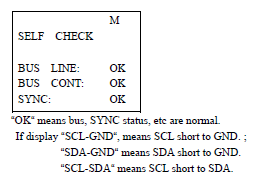
3.4 “Self-check“function check
Press “SELF-CHECK“button, the screen will display the following information:
3.5 Picture and sound check
3.5.1 Receive standard TV signal.
3.5.2 Make use of picture control buttons to check colour, contrast, brightness, sharpenss, tint’s control
function.
3.5.3 Make use of sound control buttons to check sound control function.
3.6 Sub-brightness check.
Receive A7 signal, set colour, contrast, brightness all to 0, picture left one lattice slightly lights up.
3.7 This set can produce 14 kinds of testing signals by itself. In factory menu when select some
adjustment item, every press of AV button for one time, it will produce one testing signal.
3.8 Colour purity and convergence check (in normal way).
3.9 AV terminal input/output check
3.10 Other control buttons on the set/remote controller function check.
1.1 Enter into factory adjustment menu
Press SLEEP→PIC→DSP→MENU button on the remote controller in order (the period of two
press should be less than 5 seconds), the screen will appear factory alignment menu.
1.2 Factory menu operation
Repeatedly press “MENU” button,then the menu will enter into PAGE 1→PAGE 2→PAGE
3→PAGE 4→PAGE 5 and recycle; press ▲ or ▼ button can select adjustment items upward or
downward, and press ◄ or ► button to confirm or adjust the item’s value.
1.3 To exit the factory menu
Press “SLEEP” button to exit the factory adjustment menu.
2 China 15581 Adjustment method
2.1 B+ voltage adjustment
a) Make sure the power supply is AC120 V/60 Hz (for America or Canada area).
b) Connect the digital voltmeter to B+ testing point,receive A7 signal, set the picture control to
“ NATURAL” status, adjust RP501 to make B+ voltage be 145 V±0.3 V (just for TOSHIBA
pure flat CRT, as regards to other CRT, B+ value will be marked on the parts list.)
c) In STAND BY mode, the B+ voltage will be about 84 V.
2.2 OSD position adjustment
Receive NTSC signal, change the factory adjustment menu page 3 OSD item’s value to make user’s
menu be in screen’s center position.
2.3 China 15581 AGC adjustment
a) Receive 60 dB split field (or grey-scale) signal.
b) Use oscilloscope or digital voltmeter to monitor tuner 1 pin’s voltage (RFAGC pin).
c) Select factory adjustment menu page 4 R-AGC item, making use of [←][→] button to increase the
value from down to up until the voltage just reach 4.0 V,at this time picture noisy spots should
disappear basically. Otherwise continue to fine tune R-AGC item.
d) Exit the factory menu.
China 15581 TV Service menu
Photo credit : meddiodesign.com
2.4 China 15581 Focus adjustment
2.4.1 Receive A12 signal, set picture mode to “MEMORY 2”status.
2.4.2 Adjust FBT FOCUS potentiometer to make screen’s B area’s focus optimum.
2.5 Screen-grid voltage, white balance adjustment
2.5.1 Receive A7 split field signal, set picture mode to “MEMORY 3“ status.
2.5.2 Keep RCUT’s value, not change it (for example set it to 60), roughly adjust GCUT and BCUT
value to make white balance basically normal.
2.5.3 Set colour, contrast to minimum, set brightness to 50. Use oscilloscope to monitor CRT board red
gun waveform, adjust PAGE 4 BRTS value to make black level be 180 V.
2.5.4 Adjust SCREEN (accelerating electrode) potentiometer to make picture brighten 4 lattices.
2.5.5 Fine adjust white balance (colour temperature: 12000K±8MPCD X=0.270±0.008
Y=0.283±0.008).
2.5.6 Adjust PAGE 2 BRTN value to make colour , brightness, contrast all be minimum, picture“white
block“slightly lights up.
2.6 Horizontal, vertical scanning center adjustment
2.6.1 PAL (50 Hz) horizontal、vertical center adjustment
Receive G23 signal, set picture mode to “MEMORY 2“status, fine tune vertical center VP50,
horizontal center HPOS, to make picture center be in accordance with screen center.
2.6.2 NTSC (60 Hz) H-center, V-center adjustment
Receive A6 signal, set picture mode to “MEMORY 2“ status, adjust V-center VP60, H-center HPS,
to make picture center be in accordance with screen center.
2.7 Vertical scanning amplitude adjustment
2.7.1 PAL (50 Hz) vertical amplitude adjustment
Receive D35 signal, set picture mode to “MEMORY 2“ status, adjust vertical amplitude HIT, to
make picture up/down overscanning be screen size’s 8%.
2.7.2 NTSC (60 Hz) vertical amplitude adjustment
Receive A12 signal, set picture mode to “MEMORY 2“ status, adjust V-amplitude HITS, to make
picture up/down overscanning be screen size’s 8%.
2.8 Raster correction adjustment、H-amplitude adjustment
2.8.1 PAL (50 Hz) raster correction adjustment , H-amplitude adjustment.
Receive PAL white crosshatch signal, set picture mode to “MEMORY 2“ status, adjust DPC to
make raster distortion be in minimum, adjust WID to make picture left/right overscanning be
screen size’s 8%.
2.8.2 NTSC (60 Hz) raster correction adjustment
Receive NTSC A21 signal, set picture mode to “MEMORY 2“ status, adjust DPCS to make raster
distortion minimum, adjust WIDS to make picture left/right overscanning be screen size’s 8%.
2.9 If scanning linearity distortion and raster geometrical distortion can not reach the requirements, and
if necessary, can make use of factory adjustment menu to adjust the following items:
VLIN V-linearity adjustment (PAL)
VLIS V-linearity adjustment (NTSC)
VSC Vertical S-correction adjustment (PAL)
VSS Vertical S-correction adjustment (NTSC)
CNRT Top corners’ correction
CNRB Bottom corners’ correction
KEY Trapezoid correction (PAL)
KEYS Trapezoid correction (NTSC)
2.10 Maximum sound output power
Receive single tone signal, set volume to maximum, the sound output power is 2×8 W. (can fine
adjust factory menu V100).
3 Checking points
3.1 High voltage check
3.1.1 Connect high voltmeter to CRT second anode and GND.
3.1.2 Receive A7 signal, set picture mode to “MEMORY 2“ status, measure the high voltage value, the
reading should be 30.0 kV±1 kV.
3.1.3 When setting brightness and contrast to minimum(zero beam current),measure the high voltage
value, the reading should not exceed 32 kV.
3.2 CRT filament voltage check
Receive A7 signal, set picture mode to “NATURAL“ status, use effective value voltmeter to
measure CRT filament voltage, the reading should be (6.3±0.3)Vrms.
3.3 X-ray protection check
3.3.1 Receive A7 signal, set picture mode to “MEMORY 2“ status.
3.3.2 Short S301, X-ray protection circuit should effect.
3.4 “Self-check“function check
Press “SELF-CHECK“button, the screen will display the following information:
3.5 Picture and sound check
3.5.1 Receive standard TV signal.
3.5.2 Make use of picture control buttons to check colour, contrast, brightness, sharpenss, tint’s control
function.
3.5.3 Make use of sound control buttons to check sound control function.
3.6 Sub-brightness check.
Receive A7 signal, set colour, contrast, brightness all to 0, picture left one lattice slightly lights up.
3.7 This set can produce 14 kinds of testing signals by itself. In factory menu when select some
adjustment item, every press of AV button for one time, it will produce one testing signal.
3.8 Colour purity and convergence check (in normal way).
3.9 AV terminal input/output check
3.10 Other control buttons on the set/remote controller function check.