All TV Service Menu Code

Electronic Repair, Manuals, Reference and TV Factory service mode

  • Home
  • Database
  • LCD
  • LED
  • CRT
  • Plasma
  • DLP
  • FORUM
  • Upload
  • Download
  • Join
  • Rss
  • Mobile
  • Panasonic TC-42P1 TV Service menu
  • Grundig TV Hotel mode
  • Zanussi 22ZT907 TV Service menu
  • Panasonic DMR-ES10P DVD Service menu
  • Grundig Chassis 22.1 TV Service menu
  • Grundig Chassis D6 TV Service menu
  • Panasonic TX-15LT2Z TV Service menu
  • Hisense K15 Series TV Service Menu
  • Insignia NS LCD37HD-09 TV Service menu
  • Vestel All model TV Service menu

Vizio TV Service Menu

LCD | Author | November 16, 2020

Vizio TV Service menu mode Instructions

To Enter Vizio TV Service Menu, the original remote control required, you can not do it with just the buttons on the front of the television. If your remote control lost or you can not opperate it coz broken/damage, we recommend that you buy the new one in in electronic store near of you city or purchase a replacement remote control online like a alibaba or ebay before trying to enter the Vizio TV Service . 


Enter Vizio TV Service mode First way

Turn off yor television unit.
Press and hold the button of (CH +) and (CH -) on the Television pannel.
Press and release the MAIN POWER switch on the television.
Release the (CH +) and (CH -) buttons you pressed.
On the remote control Press the MENU button .
Regular appear on the screen, you see a "F" in the bottom right corner of screen.

After menu appear on the screen
Press and hold the MENU key/button for few seconds and release a button
The Vizio TV Service Menu will be displayed on the screen.

If the metod above not work for your television , please use the mothod below

Second way to Enter Vizio TV Service mode

Press sequentially the MENU 2,4,8,9  key/button on the remote control.
After seccusfully entered the number, you will see the Service mode menu will be displayed on the screen. You can set the menu by pressing volume up down and select parametter use channel button.
To save the parameter press the EXIT button.

Third way to Enter Vizio TV Service mode

Press sequentially the MENU 1,2,3 buttons on the remote control to enter service mode.
After seccusfully entered the number, you will see the Service mode menu will be displayed on the screen. You can set the menu by pressing volume up down and select parametter use channel button.To save the parameter press the EXIT button.
Fourth way to Enter Vizio TV Service mode

Press sequentially the 1,2,3 buttons on the remote control after your press and hold the EXIT button on the remote unit for 3 seconds.

After seccusfully entered the number, you will see the Service mode menu will be displayed on the screen. You can set the menu by pressing volume up down and select parametter use channel button.To save the parameter press the EXIT button.

Last way for Vizio TV P-Series and D-Series


Press sequentially the MENU 1,9,9,9,Return buttons on the remote control.
After seccusfully entered the number, you will see the Service mode menu will be displayed on the screen. You can set the menu by pressing volume up down and select parametter use channel button.To save the parameter press the EXIT button. 


Vizio TV Service mode

Vizio TV Service Menu mode


Model #: VIZIO VX37L HDTV

IBM and IBM products are registered trademarks of International Business Machines
Corporation.
Macintosh and Power Macintosh are registered trademarks of Apple Computer, Inc.
VINC and VINC products are registered trademarks of V, Inc.
VESA, EDID, DPMS and DDC are registered trademarks of Video Electronics Standards
Association (VESA).
Energy Star is a registered trademark of the US Environmental Protection Agency (EPA).
No part of this document may be copied, reproduced or transmitted by any means for any
purpose without prior written permission from VINC.
FCC INFORMATION
This equipment has been tested and found to comply with the limits of a Class B digital device,
pursuant to part 15 of the FCC Rules. These limits are designed to provide reasonable protection against harmful interference in a residential installation. This equipment generates, uses and can radiate radio frequency energy, and if not installed and used in accordance with the instructions, may cause harmful interference to radio communications. However, there is no guarantee that the interference will not occur in a particular installation. If this equipment does cause unacceptable interference to radio or television reception, which can be determined by turning the equipment off and on, the user is encouraged to try to correct the interference by one or more of the following measures -- reorient or relocate the receiving antenna; increase the separation between equipment and receiver; or connect the into an outlet on a circuit different from that to which the receiver is connected.


FCC WARNING
To assure continued FCC compliance, the user must use a grounded power supply cord and the provided shielded video interface cable with bonded ferrite cores. Also, any unauthorized changes or modifications to Amtrak products will void the user’s authority to operate this device. Thus VINC Will not be held responsible for the product and its safety.


CE CERTIFICATION
This device complies with the requirements of the EEC directive 89/336/EEC with regard to
“Electromagnetic compatibility.”


SAFETY CAUTION
Use a power cable that is properly grounded. Always use the AC cords as follows – USA (UL);
Canada (CSA); Germany (VDE); Switzerland (SEV); Britain (BASEC/BS); Japan (Electric
Appliance Control Act); or an AC cord that meets the local safety standards. 


1. LCD CHARACTERISTICS
Type: LPL LC370WX1-SLA1
Size: 3702inch
Display Size: 37.02 inches (940.3mm) diagonal
Outline Dimension: 877.0 mm (H) x 516.8 mm (V) x 55.5 mm (D) (Typ.)
Pixel Pitch: 0.200mm x 0.600mm x RGB
Pixel Format: 1366 horiz. By 768 vert. Pixels RGB strip arrangement
Contrast ratio: 1.CR : 1000(Typ) 2. CR WITH AI : 2000(Typ)
Luminance, White: 500 cd/m2 (Typ)
Display Operating Mode: normally Black
Surface Treatment: Hard Coating (3H) ,Anti-glare treatment of the front polarizer.
2. OPTICAL CHARACTERISTICS
Viewing Angle (CR>10)
Left: 89°typ.
Right: 89°typ.
Top: 89°typ.
Bottom: 89°typ.
3. SIGNAL (Refer to the Timing Chart)
Sync Signal
1) Type: TMDS
2) Input Voltage Level: 90~240 Vac, 50/ 60 Hz
4.Input Connectors
RJ11, D-SUB15PIN (MINI, 3rows), Headphone, HDMIX2, RCAX3 (component),
RCAX2 (AUDIO in), RCAX3 (composite), RCAX2 (AUDIO in), S-Video, Tuner.
5. POWER SUPPLY
Power Consumption: 280W MAX
Power OFF: to less than 3W MAX

6.Speaker
Output 10W (max) X2
7. ENVIRONMENT
5-1. Operating Temperature: 5c~35c (Ambient)
5-2. Operating Humidity: Ta= 35 °C, 90%RH (Non-condensing)
5-3. Operating Altitude: 0 - 14,000 feet (4267.2m)(Non-Operating)
8. DIMENSIONS (Physical dimension)
Width: 800 mm. +/- 20 mm
Depth: 1060 mm +/- 20 mm
Height: 360 mm +/- 20 mm
9. WEIGHT (Physical weight)
a. Net: 19.1+/-0.5kgs
b. Gross: 24.6+/-0.5kgsn
9-1. MOUNTING PRECAUTIONS
(1) You must mount a module using holes arranged in four corners or four sides.
(2) You should consider the mounting structure so that uneven force (ex. Twisted
stress) is not applied to the module. And the case on which a module is mounted
should have sufficient strength so that external force is not transmitted directly to
the module.
(3) Please attach the surface transparent protective plate to the surface in order to
protect the polarizer.
Transparent protective plate should have sufficient strength in order to the resist external force.
(4) You should adopt radiation structure to satisfy the temperature specification.
(5) Acetic acid type and chlorine type materials for the cover case are not desirable
because the former generates corrosive gas of attacking the polarizer at high temperature and the latter causes circuit break by electro-chemical reaction.
(6) Do not touch, push or rub the exposed polarizes with glass, tweezers or anything
harder than HB pencil lead. And please do not rub with dust clothes with chemical treatment.
Do not touch the surface of polarizer for bare hand or greasy cloth.(Some cosmetics are detrimental to the polarizer.)

(7) When the surface becomes dusty, please wipe gently with absorbent cotton or other soft materials like chamois soaks with petroleum benzene. Normal-hexane is recommended for cleaning the adhesives used to attach front / rear polarizers.
Do not use acetone, toluene and alcohol because they cause chemical damage to the polarizer.
(8) Wipe off saliva or water drops as soon as possible. Their long time contact with polarizer causes deformations and color fading.
(9) Do not open the case because inside circuits do not have sufficient strength.
9-2. OPERATING PRECAUTIONS
(1) The spike noise causes the mis-operation of circuits. It should be lower than following voltage :
V=±200mV(Over and under shoot voltage)
(2) Response time depends on the temperature. (In lower temperature, it becomes longer.)
(3) Brightness depends on the temperature. (In lower temperature, it becomes lower.)And in lower temperature, response time (required time that brightness is stable after turned on) becomes longer.
(4) Be careful for condensation at sudden temperature change. Condensation makes damage to polarizer or electrical contacted parts. And after fading condensation, smear or spot will occur.
(5) When fixed patterns are displayed for a long time, remnant image is likely to occur.
(6) Module has high frequency circuits. System manufacturers shall do sufficient suppression to the electromagnetic interference. Grounding and shielding methods may be important to minimize the interference.

9-3. HANDLING PRECAUTIONS FOR PROTECTION
(1) The protection film is attached to the bezel with a small masking tape. When the protection film is peeled off, static electricity is generated between the film and polarizer. This should be peeled off slowly and carefully by people who are electrically grounded and with well ion-blown equipment or in such a condition,etc.
(2) When the module with protection film attached is stored for a long time,
sometimes there remains a very small amount of glue still on the bezel after the protection film is peeled off.
(3) You can remove the glue easily. When the glue remains on the bezel surface or its vestige is recognized, please wipe them off with absorbent cotton waste or other soft material like chamois soaked with normal-hexane.

COPYRIGHT © 2000 V, INC. ALL


LG 42LK450-UB TV Service Menu

LCD | Author | April 20, 2020

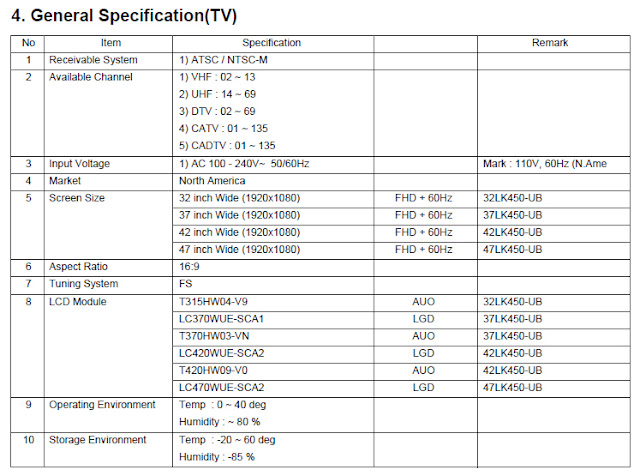
SPECIFICATION LG 42LK450-UB TV LCD
NOTE : Specifications and others are subject to change without notice for improvement.

#1. Application range
This spec sheet is applied LCD TV with 32”, 37”, 42”, 47”, 55”
LA01U chassis.
#2. Requirement for Test
Each part is tested as below without special appointment.
1) Temperature: 25 ºC ± 5 ºC
2) Relative Humidity: 65 ± 10 %
3) Power Voltage : Standard input voltage(100-240V~, 50/60Hz)
* Standard Voltage of each product is marked by models
4) Specification and performance of each parts are followed
each drawing and specification by part number in
accordance with BOM.
5) The receiver must be operated for about 5 minutes prior to
the adjustment.

#3. Test method
1) Performance: LGE TV test method followed
2) Demanded other specification
- Safety : UL, CSA, IEC specification
- EMC: FCC, ICES, IEC specification

LG 42LK450-UB TV factory mode

LG 42LK450-UB TV Service Menu


LG 42LK450-UB TV Service Menu
1. Application range LG 42LK450-UB
This spec. sheet applies to LA01U Chassis applied LED LCD
TV all models manufactured in TV factory.

2. Specification
2.1 Because this is not a hot chassis, it is not necessary to use an isolation transformer. However, the use of isolation transformer will help protect test instrument.
2.2 Adjustment must be done in the correct order.
2.3 The adjustment must be performed in the circumstance of 25±5°C of temperature and 65±10% of relative humidity 2.4 The input voltage of the receiver must keep 100~240V~, 50/60Hz.
2.5 At first Worker must turn on the SET by using Power Only key.
2.5 The receiver must be operated for about 5 minutes prior to the adjustment when module is in the
circumstance of over 15.
In case of keeping module is in the circumstance of 0°C, it should be placed in the circumstance of above 15°C for 2 hours In case of keeping module is in the circumstance of below -20°C, it should be placed in the circumstance of above 15°C for 3 hours.
• Caution
When a still image is displayed for 20 minutes or longer (especially where W/B scale is strong. Digital pattern 13ch and/or Cross hatch pattern 09ch), there can some afterimage in the black level area.

3. Adjustment items LG 42LK450-UB TV Service Menu
3.1 Board Level Adjustment
(1) Adjust 480i Comp1(ADC)
(2) EDID/DDC download
• Remark
- Above adjustment items can be also performed in Final Assembly if needed. Adjustment items in both PCBA and final assembly stages can be checked by using the INSTART Menu 1.ADJUST CHECK.
3.2 Final Assembly adjustment
(1) White Balance adjustment
(2) RS-232C functionality check
(3) Factory Option setting per destination
(4) Shipment mode setting (IN-STOP)
3.3 Etc
(1) Ship-out mode
(2) Service Option Default
(3) USB Download(S/W Update, Option, Service only)
(4) ISP Download (Optional)

4. Board Level Adjustment LG 42LK450-UB TV Service Menu
4.1. ADC Adjustment
4.1.1. Overview
• ADC adjustment is needed to find the optimum black level and gain in Analog-to-Digital device and to compensate RGB deviation.
4.1.2. Equipment & Condition
1) Jig (RS-232C protocol)
• Required equipment : Adjustment R/C
*Enter Service Mode by pushing “ADJ” key,
*Enter Internal ADC mode by pushing “G” key at “6. ADC
Calibration”
4.1.3. Adjustment
4.1.3.1 Adjustment method
• Using RS-232, adjust items listed in 3.1 in the other shown in “4.1.3.3”
3. Adjustment items
3.1 Board Level Adjustment
(1) Adjust 480i Comp1(ADC)
(2) EDID/DDC download
• Remark
- Above adjustment items can be also performed in Final
Assembly if needed. Adjustment items in both PCBA and
final assembly stages can be checked by using the INSTART Menu 1.ADJUST CHECK.
3.2 Final Assembly adjustment
(1) White Balance adjustment
(2) RS-232C functionality check
(3) Factory Option setting per destination
(4) Shipment mode setting (IN-STOP)
3.3 Etc
(1) Ship-out mode
(2) Service Option Default
(3) USB Download(S/W Update, Option, Service only)
(4) ISP Download (Optional)


Sansui 3200D TV Service Menu

LCD | Author | April 19, 2020

SANSUI HD LCD 3200D TV Service menu mode

32" WIDE TFT LCD TELEVISION
WITH DIGITAL TUNER

Operating the receiver outside of its cabinet or with its back removed involves a shock hazard. Work on these models should only be performed by those who are thoroughly familiar with precautions necessary when working on high voltage equipment.
Exercise care when servicing this chassis with power applied. Many B plus and high voltage RF terminals are exposed which, if carelessly contacted, can cause serious shock or result in damage to the chassis.
Maintain interconnecting ground lead connections between chassis, escutcheon, picture tube dag and
tuner cluster when operating the chassis These receivers have a "polarized" AC line cord. The AC
plug is designed to fit into standard AC outlets in one direction only. The wide blade connects to the "ground side" and the narrow blade connects to the "hot side" of the AC line. This assures that the TV receiver is properly grounded to the house wiring. If an extension cord must be used, make sure it is of the "polarized" type.
Since the chassis of this receiver is connected to one side of the AC supply during operation, service should not be attempted by anyone not familiar with the precautions necessary when working on these types of equipment When it is necessary to make measurements or tests with
AC power applied to the receiver chassis, an Isolation Transformer must be used as a safety precaution and to prevent possible damage to transistors. The Isolation Transformer should be connected between the TV line cord plug and the AC power outlet.
When removing springs or spring mounted parts from the tuner, tuner cluster or chassis, shatterproof goggles must be worn. Keep others without shatterproof goggles away.
Before returning the receiver to the user, perform the following safety checks:
1 Inspect all lead dress to make certain that leads are not pinched or thai hardware is not lodged between the chassis and other metal parts in the receiver
2 Replace all protective devices such as nonmeiallic control knobs, Insulating fishpapers. cabinet backs adjustment and compartment covers or shields, isolation resistor-capacitor networks, mechanical Insulators, etc
3 To be sure that no shock hazard exists, a check for the presence of leakage current should be made at each exposed metal part having a return path to the chassis (antenna, cabinet metal, screw heads,
knobs and-'or shafts, escutcheon, etc ) In the following manner Mug the AC line cord directly into a 120V AC receptacle.
(Do not use an Isolation Transformer dunng these checks) All checks must be repeated with the AC line record plug connection reversed, (if necessary, anonpolarized adapter plug must be used only for the purpose of completing these checks.)
If available, measure current using an accurate leakage current (ester Any reading of 0 35mA or more is excessive and indicates a potential shock hazard which must be corrected before returning the receiver to the owner If a reliable leakage current tester is not available, this alternate method of measurement should be used Using two clip leads, connect a 1500 ohm. 10 watt resistor paralleled by a 0.15uF capacitor in series with a known earth ground, such as a water pipe or conduit and the metal part to be checked Use a VTVM or VOM with 1000 ohms pe* volt, or higher, sensitivity to rne.-.F.!.-* 1 hi f- AC vc la^f. d'op .=cross :ie re&is:or Ary readmg of 035 volt RMS or more is excessive and Indicates a potential shock hazard which must be corrected before returning the receiver to the owner

Sansui HDLCD3200D TV Service Menu


WHEN REPLACING EEPROM (MEMORY) IC Sansui HDLCD3200D
CONFIRMATION OF CHECK SUM, POWER ON TOTAL HOURS AND MICON VERSION
Initial total of MEMORY IC. POWER ON total hours and MICON VERSION can be checked on the screen. Total houis are
displayed in 16 system of notation
NOTE: If you set a factory Initialization, the total hours Is reset to "0".
Please refer to 'CONFIRMATION OF INITIAL DATA" when SUM DATA is not corresponding.
1. Turn on the POWER, and set to the TV mode
2 Set the VOLUME to minimum.
3. Press both VOL DOWN button on the set and Channel button (8) on the remote control for more than 2 seconds.
4 After the confirmation of each check sum. turn off the power
NOTE The each item value might be different according to each set|

CONFIRMATION OF INITIAL DATA
If a service repair is undertaken where it has been required to change the MEMORY IC, the following steps should be
taken to ensure correct data settings while making reference to INITIAL SETTING TABLE (Attached "INITIAL DATA").
1. Turn on the POWER, and set to the TV mode
2. Set the VOLUME to minimum.
3   Press both VOL DOWN button on the set and Channel button (6) on the remote control for more than 2 seconds
4 ADDRESS is now selected and should "blink" Using Ihe UP/DOWN buton on the remote, step through the ADDRESS
until required ADDRESS to be changed is reached.
5 Press LEFT/RIGHT button to select DATA When DATA -s selected. It will "blink".
6. Again, step through the DATA using UP/DOWN button until required DATA value has been selected
7 Pressing LEFT/RIGHT button will take you back to ADDRESS lor further selection if necessary
8 Repeat steps 4 to 6 until all data has been checked
9. When satisfied correct DATA has been entered, turn POWER off (return to STANDBY MODE) to finish DATA input.
After the data input, set to the initializing of shipping.
10 Turn on the POWER, and set to the TV mode.
11 Press both VOL. DOWN button on the set and Channel button (1) on Ihe remote control for more than 2 seconds
12. After the finishing of the initializing of shipping, the unit will turn off automatically
The unit will now have the correct DATA for the new MEMORY IC.


Sansui 1909 TV Service Menu

LCD | Author | April 18, 2020

SERVICE MODE SANSUI HD LCD 1909

ORIGINAL CODE NO. M39A05WASM
19" WIDE TFT LCD TELEVISION WITH DIGITAL TUNER
VERSION (B) DATE OF ISSUE 8/2009 All the
Tfi is unit is provided with the following SERVICE MODES so you can repair, examine and adjust easily.
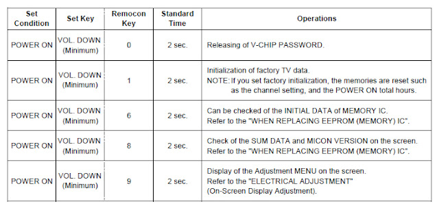
To enter to the SERVICE MODE function, press and hold both buttons simultaneously on the main unit and on the remote
control for more than a the standard time in the appropriate condition. (See below chart.)

Set Condition    Set Key    Remocon Key    Standard Time    Operations
POWER ON    VOL. DOWN (Minimum)    0    2 sec.    Releasing of V-CHIP PASSWORD.
POWER ON    VOL. DOWN (Minimum)    i 1    2 sec.    Initialization of factory TV data. NOTE: if you set factory initialization, the memories are reset such as the channel setting, and the POWER ON total hours.
POWER ON    VOL. DOWN (Minimum)    i 6    2 sec.    Can be checked of the INITIAL DATA of MEMORY IC Refer to the "WHEN REPLACING EEPROM (MEMORY) IC".
POWER ON    VOL. DOWN (Minimum)    i i i 8    2 sec.    Check of the SUM DATA and MICON VERSION on the screen. Refer to the "WHEN REPLACING EEPROM (MEMORY) IC".
POWER ON    VOL. DOWN (Minimum)    I i 9 i    2 sec.    Display of the Adjustment MENU on the screen. Refer to the "ELECTRICAL ADJUSTMENT (On-Screen Display Adjustment).


SANSUI HDLCD1909 TV Service Menu


WHEN REPLACING EEPROM (MEMORY) IC SANSUI HD LCD 1909 TV
CONFIRMATION OF CHECK SUM, POWER ON TOTAL HOURS AND MICON VERSION
Initial total of MEMORY IC, POWER ON total hours and MICON VERSION can be checked on the screen. Total hours are displayed in 16 system of notation.
NOTE: If you set a factory initialization, the total hours is reset to "0".
Please refer to "CONFIRMATION OF INITIAL DATA" when SUM DATA is not corresponding.
1. Turn on the POWER, and set to the ALL mode.
2. Set the VOLUME to minimum.
3. Press both VOL. DOWN button on the set and Channel button (8) on the remote control for more than 2 seconds.
4. After the confirmation of each check sum, turn off the power.
NOTE: The each item value might be different according to each set.

CONFIRMATION OF INITIAL DATA SANSUI HDLCD1909 TV
If a service repair is undertaken where it has been required to change the MEMORY IC, the following steps should be taken to ensure correct data settings while making reference to INITIAL SETTING TABLE (Attached "INITIAL DATA").
1. Turn on the POWER, and set to the ALL mode.
2. Set the VOLUME to minimum.
3. Press both VOL. DOWN button on the set and Channel button (6) on the remote control for more than 2 seconds.
ADDRESS and DATA should appear
NOTE: No need to set data other position than 0D00~0EFF.
4. ADDRESS is now selected and should "blink". Using the CH. UP/DOWN buton on the remote, step through the ADDRESS
until required ADDRESS to be changed is reached.
5. Press VOL. UP/DOWN button to select DATA. When DATA is selected, it will "blink".
6. Again, step through the DATA using CH. UP/DOWN button until required DATA value has been selected.
7. Pressing VOL. UP/DOWN button will take you back to ADDRESS for further selection if necessary.
8. Repeat steps 4 to 6 until all data has been checked.
9. When satisfied correct DATA has been entered, turn POWER off (return to STANDBY MODE) to finish DATA input After the data input, set to the initializing of shipping.
10. Turn on the Power.
11. Set the VOLUME to minimum.
12. Press both VOL. DOWN button on the set and Channel button (1) on the remote control for more than 2 seconds.
13. After the finishing of the initializing of shipping, the unit will turn off automatically.
The unit will now have the correct DATA for the new MEMORY IC.

ELECTRICAL ADJUSTMENTS SANSUI HD LCD 1909 TV
1. ADJUSTMENT PROCEDURE
Read and perform these adjustments when repairing the circuits or replacing electrical parts or PCB assemblies.
CAUTION
• Use an isolation transformer when performing any service on this chassis.
• When removing a PCB or related component, after unfastening or changing a wire, be sure to put the wire back in its original position.
• When you exchange IC and Transistor with a heat sink, apply silicon grease(YG6260M) on the contact section of the heat sink. Before applying new silicon grease, remove all the old silicon grease. (Old grease may cause damage to the IC and Transistor).
Prepare the following measurement tools for electrical adjustments.
1. Pattern Generator On-Screen Display Adjustment
1. Set the VOLUME to minimum.
2. Press the VOL. DOWN button on the set and the channel button (9) on the remote control for more than 2 seconds to display adjustment mode on the screen
3. Use the CH UP/DOWN button or Channel button (0-9) on the remote control to select the options 4. Press the MENU button on the remote control to end the adjustments.
5. To display the adjustment screen for TV, AV.COMPONENT HDMI and PC mode, press the INPUT SELECT button on the remote control.
6. Receive the DIGITAL broadcasting.
7. To display the adjustment screen fo DTV mode, select the digital channel.
8. Press the VOL.DOWN buttom on the set and the channel
(9) on the remote control for more than 2 seconds.

NO.    FUNCTION    NO.    FUNCTION
C3    R DRIVE(N)    34    BRIGHTNESS MIN
04    R CUTOFF(N)    35    TINT
05    G DRIVE(N)    36    SHARP H1 MAX
06    G CUTOFF(N)    37    SHARP H1 MIN
C7    8 DRIVE(N)    38    SHARP H2 MAX
C8    B CUTOFF(N)    39    SHARP H2 MIN
C9    R DRIVE(C)    40    SHARP H3 MAX
10    R CUTOFF(C)    41    SHARP H3 MIN
11    G DRIVE(C)    42    SHARP H4 MAX
12    G CUTOFF(C)    43    SHARP H4 MIN
13    B DRIVE(C)    44    SHARP H5 MAX
14    B CUTOFF(C)    46    SHARP H5 MIN
15    R DRIVE(W)    46    SHARP V1 MAX
16    R CUTOFF(W)    47    SHARP V1 MIN
'7    G DRIVE(W)    46    SHARP V2 MAX
ia    G CUTOFF(W)    49    SHARP V2 MIN
19    B DRIVE(W)    50    CONTRAST CENTER
20    B CUTOFF(W)    51    CONTRAST MAX
29    BAK LIGHT CENT    52    CONTRAST MIN
30    BAK LIGHT MAX    53    COLOR CENTER
31    BAK LIGHT MIN    54    COLOR MAX
33    BRIGHTNESS CENT    55    COLOR MIN
33    BRIGHTNESS MAX    58    CONTRAST 40

2. BASIC ADJUSTMENTS SANSUI HD LCD 1909 TV
2-1: WHITE BALANCE SANSUI HD LCD 1909 TV
1. Place the set in Aging Test for more than 30 minutes.
2. Receive the gray scale pattern from the Pattern Generator.
3. Press the INPUT SELECT button on the remote control to set to the AV mode.
4. Using the remote control, set the brightness and contrast to normal position.
5. Activate the adjustment mode and press the channel button (03) on the remote control to
selecf'R DRIVE (N)".
6. Press the UP/DOWN button on the remote control to select the "R CUTOFF (N)", "G DRIVE (N)",
G CUTOFF (N), "B DRIVE (N)", "B CUTOFF (N)",
R DRIVE (C), "R CUTOFF (C)", "G DRIVE (C)",
G CUTOFF (C), "B DRIVE (C)", "B CUTOFF (C)",
R DRIVE (W), "R CUTOFF (W)", "G DRIVE (W)",
G CUTOFF (W), "B DRIVE (W)" or "B CUTOFF (W)".
7. Adjust the LEF/RIGHT button on the remote control to whiten the R CUTOFF (N), G DRIVE (N),
G CUTOFF (N), B DRIVE (N), B CUTOFF (N),
R DRIVE (C), R CUTOFF (C), G DRIVE (C),
G CUTOFF (C), B DRIVE (C), B CUTOFF (C),
R DRIVE (W), R CUTOFF (W), G DRIVE (W),
G CUTOFF (W), B DRIVE (W) and B CUTOFF (W) at each step tone sections equally.
8. Perform the above adjustments 6 and 7 until the white color is achieved.


LG LED 55LW980S-ZA TV Service menu

LCD | Author | April 15, 2020
LG LED mode55LW980S-ZA TV Service menu CHASSIS : LD12D
LG LED 55LW980S-ZA TV Service menu General Guidance
An isolation Transformer should always be used during the servicing of a receiver whose chassis is not isolated from the AC power line. Use a transformer of adequate power rating as this protects the technician from accidents resulting in personal injury from electrical shocks.
It will also protect the receiver and it's components from being damaged by accidental shorts of the circuitry that may be inadvertently introduced during the service operation.
If any fuse (or Fusible Resistor) in this TV receiver is blown, replace it with the specified.
When replacing a high wattage resistor (Oxide Metal Film Resistor, over 1 W), keep the resistor 10 mm away from PCB.
Keep wires away from high voltage or high temperature parts.
Before returning the receiver to the customer, always perform an AC leakage current check on the exposed metallic parts of the cabinet, such as antennas, terminals, etc., to be sure the set is safe to operate without damage of electrical shock.
Leakage Current Cold Check(Antenna Cold Check)
With the instrument AC plug removed from AC source, connect an electrical jumper across the two AC plug prongs. Place the AC switch in the on position, connect one lead of ohm-meter to the AC
plug prongs tied together and touch other ohm-meter lead in turn to each exposed metallic parts such as antenna terminals, phone jacks, etc.
If the exposed metallic part has a return path to the chassis, the measured resistance should be between 1 MΩ and 5.2 MΩ.
When the exposed metal has no return path to the chassis the reading must be infinite.
An other abnormality exists that must be corrected before the receiver is returned to the customer.

Leakage Current Hot Check (See below Figure)
Plug the AC cord directly into the AC outlet.
Do not use a line Isolation Transformer during this check.
Connect 1.5 K / 10 watt resistor in parallel with a 0.15 uF capacitor between a known good earth ground (Water Pipe, Conduit, etc.)
and the exposed metallic parts.
Measure the AC voltage across the resistor using AC voltmeter with 1000 ohms/volt or more sensitivity.
Reverse plug the AC cord into the AC outlet and repeat AC voltage measurements for each exposed metallic part. Any voltage measured must not exceed 0.75 volt RMS which is corresponds to 0.5 mA.
In case any measurement is out of the limits specified, there is possibility of shock hazard and the set must be checked and repaired before it is returned to the customer.
Leakage Current Hot Check circuit


LG LED 55LW980S-ZA TV Service menu


3. Automatic Adjustment
3.1. ADC Adjustment
(1) Overview
ADC adjustment is needed to find the optimum black level and gain in Analog-to-Digital device and to compensate RGB deviation.
* If Adjust ADC is “OTP”, It doesn’t need ADC adjustment.
(GP3-BCM)
(2) Equipment & Condition
1) Jig (RS-232C protocol)
2) MSPG-925 Series Pattern Generator(MSPG-925FA, pattern - 65)
- Resolution : 480i Comp1 1080P Comp1 1920*1080 RGB
- Pattern : Horizontal 100% Color Bar Pattern
- Pattern level : 0.7 ± 0.1 Vp-p
- Image


LG 47LM6610 LED LCD TV

LCD | Author | April 14, 2020
LG 47LM6610 LED LCD TV CHASSIS : LB22E
MODEL : 47LM6610/661Y/6690
MODEL : 47LM6610/661Y-TB 47LM6690-TC

IMPORTANT SAFETY NOTICE
Many electrical and mechanical parts in this chassis have special safety-related characteristics. These parts are identified by in the
Schematic Diagram and Exploded View.
It is essential that these special safety parts should be replaced with the same components as recommended in this manual to prevent
Shock, Fire, or other Hazards.
Do not modify the original design without permission of manufacturer.


 LED LCD TV LG 47LM6610

LG 47LM6610 LED LCD TV


* USB DOWNLOAD(*.epk file download)
(1) Put the USB Stick to the USB socket.
(2) Automatically detecting update file in USB Stick.
- If your downloaded program version in USB Stick is Low, it didn't work. But your downloaded version is High, USB data is automatically detecting.
(3) Show the message "Copying files from memory".
(5) Updating Completed, The TV will restart automatically.
(6) If your TV is turned on, check your updated version and Tool option. (explain the Tool option, next stage)
* If downloading version is more high than your TV have, TV can lost all channel data. In this case, you have to channel recover. if all channel data is cleared, you didn’t have a DTV/ATV test on production line.
* After downloading, have to adjust Tool Option again.
(1) Push "IN-START" key in service remote control.
(2) Select "Tool Option 1" and push "OK" key.
(3) Punch in the number. (Each model has their number)
3.1. ADC Process
- Enter Service Mode by pushing "ADJ" key,
- Enter ADC mode by pushing "►" key at "8. ADC Calibration".
- There are 2 ways for ADC Calibration.(OTP, External)
OTP mode: Automatic ADC Calibration.(Internal ADC Calibration)
On the manufacture line, OTP is used for ADC Calibration automatically.
Externl mode: Manual ADC Calibration. When OTP mode is failed, ADC calibration should be “OK” by using External mode.
3.1.1. OTP mode
(1) Press "ADJ" key on the Adjustment Remote Control, then select “8. ADC Calibration”. By pressing Enter key, enter ADC Calibration menu.
(2) Set up the ADC Type to OTP, then Select [Start] button by pressing Enter key, Component and RGB are Written and display Success or NG.

Enter Service menu LG 47LM6610 LED LCD TV


3.1.2. External mode
* Equipment: MSPG-925 series Pattern Generator , RS-232C Jig
(1) Input the signal for TV SET by using Pattern Generator
(Model : 225, Pattern No : 65)_1080P
(2) Change the ADC type “External” by using “►”key.
(3) Enter “Start” key.
(4) Check the sign “OK” all of comp/RGB.
- Pattern : Horizontal 100% Color Bar Pattern
- Pattern level : 0.7±0.1 Vp-p
- Image
Adjust Sequence
▪ aa 00 00 [Enter Adjust Mode]
▪ xb 00 40 [Component1 Input (480i)]
▪ ad 00 10 [Adjust 480i Comp1]
▪ xb 00 60 [RGB Input (1024*768)]
▪ ad 00 10 [Adjust 1024*768 RGB]
▪ aa 00 90 End Adjust mode
* Required equipment : Adjustment remote control.
3.2 Function Check
3.2.1 Check display and sound
■ Check Input and Signal items.
(1) TV
(2) AV (SCART1/SCART2/ CVBS)
(3) COMPONENT (480i)
(4) RGB (PC : 1024 x 768 @ 60hz)
(5) HDMI
(6) PC Audio In
* Display and Sound check is executed by Remote control.
<Caution>
Not to push the "INSTOP" key after completion if the function
inspection.


Panasonic TC-32LX70 TV Service menu

LCD | Author | April 13, 2020

Panasonic TC-32LX70 LCD TV Service menu mode

Over-Current Protection Circuit 2

Sound_VCC Protection
During normal operation, the 24 volt output of the P board biases the transistor Q7208 into conduction, causing its collector to become low. The low at the collector of Q7208 causes the transistor Q7214 to turn off. When the PANEL_MAIN_ON command (high) is issued Q7212 turns on. Consequently Q7225 turns off, and IC7215 goes into conduction to provide the SOUND_15V output.
When the 24 drops below the reverse breakdown voltage of D7206, Q7208 turns off, Q7214 turns on to ground the PANEL_MAIN_ON voltage. Q7212 turns off and Q7225 turns on. IC7215 ceases to operate and the Sound_VCC is no longer output.
During normal operation, the anode of D7469 receives 5V and the junction of D7469, D7470, R7486,
and R7492 receives 12V. Due to this condition, the transistor Q7210 remains off. If the SOUND_15V line becomes shorted, diode D7469 goes into conduction to turn Q7210 on. Consequently Q7210 outputs a high to shut down the unit.
Panel_VCC Protection During normal operation, the 24 volt output of the P board biases the transistor Q7208 into conduction,
causing its collector to become low. The low at the collector of Q7208 causes the transistor Q7508 to turn off. When
the PANEL_VCC_ON command (high) is issued, Q7702 turns on. Consequently Q7701 turns off, and IC7212 goes into conduction to provide the PANEL_12V output.
When the 24 drops below the reverse breakdown voltage of D7206, Q7208 turns off, Q7508 turns on to ground the PANEL_VCC_ON voltage. Q7702 turns off, and Q7701 turns on. IC7212 ceases to operate and the Panel_VCC is no longer output.
During normal operation, the anode of D7472 receives 5V and the junction of D7472, D7473, R7493,
and R7488 receives 12V. Due to this condition, the transistor Q7210 remains off. If the Panel_12V line becomes shorted, diode D7472 goes into conduction to turn Q7210 on. Consequently Q7210 outputs a high to shut down the unit.
When the unit is turned on, the TV_Main_On command (high) of IC1100 biases the transistor Q7212 into operation, causing its collector to become “low”. The low at the collector of Q7212 causes the transistors Q7225 to turn off. As a result, IC7215 goes into operation to provide the Sound_15V output.


1. Checks the communication IIC bus lines
2. Provides a SOS History
To Access the Self-Check Mode: Turn the TV on and select an active channel. While pressing the “VOLUME ( - )” button on the main unit, press the “OK” button on the remote control for more than 3 seconds.
This procedure is useful to display the unit’s firmware version and check IC data communications.
The Self-Check function clears channel programmed settings, picture settings, channel labels, LOCK mode settings, and password. It restores the unit to factory shipping settings.

 LCD TV Service menu Panasonic TC-32LX70

Panasonic TC-32LX70 LCD TV Service menu


Panasonic TC-32LX70 LCD check point

To enter the factory Mode, turn the TV on and while pressing the 'VOLUME (-)" button on the main unit, press the "RECALL" button of the remote control three times within 3 seconds.
To exit the factory Mode. Press the Power button on the TV or the Remote Control.

Panasonic TC-32LX70 LCD factory mode
Adjustment Data
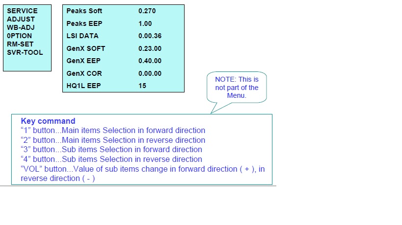
“1” or “2” button of the remote control to select the main Adj. item
“3” or “4” button of the remote control to select the sub Adj. Item
“Vol. (-)” or” Vol. (+)” to change the data

Note: Record the original data on a sheet of paper prior to making any adjustment.

To access SRV-TOOL:
1. Select “SRV-TOOL” in the factory Mode menu.
2. Press the [OK] button on the remote control.


LG 42LM6400 CA TV Service menu

LCD | Author | April 12, 2020

LG LED LCD TV 42LM6400 & 42LM6400-CA

CHASSIS MODEL: LC22E

CAUTION!
BEFORE SERVICING THE CHASSIS or ACCESS THE FACTORY MODE,
READ THE SAFETY PRECAUTIONS IN YOUR SERVICE MANUALS.


1. Application Range LG LED LCD TV 42LM6400 & 42LM6400-CA
This specification sheet is applied to all of the LED LCD TV with LC22E chassis.
2. Designation
(1) ecause this is not a hot chassis, it is not necessary to use an isolation transformer. However, the use of isolation transformer will help protect test instrument.
(2) Adjustment must be done in the correct order.
(4) The input voltage of the receiver must keep 100~240V, 50/60Hz.
(5) The receiver must be operated for about 5 minutes prior to
the adjustment when module is in the circumstance of over 15.
In case of keeping module is in the circumstance of 0 °C, it should be placed in the circumstance of above 15 °C for 2 hours In case of keeping module is in the circumstance of below -20°C, it should be placed in the circumstance of above 15 °C for 3 hours.
(3) The adjustment must be performed in the circumstance of 25 ±5 C of temperature and 65±10% of relative humidity if there is no specific designation.
Cauti on) When still image is displayed for a period of 20 minutes or longer (especially where W/B scale is strong.
Digital pattern 13ch and/or Cross hatch pattern 09ch), there can some afterimage in the black level area.

3. Adjustment items LG LED LCD TV 42LM6400 & 42LM6400-CA
3.1 Main PCB check process
MAC Address Download
Wide-Vine Key Download
Adjust 1920*1080 Compl
Adjust 1920*1080 RGB
EDID/DDC download
Above adjustment items can    also performed in Final Assembly if needed. Both Board-level and
Final assembly adjustment items can be check using in-Start Menu.
1.ADJUST CHECK.

3.2. Final assembly adjustment
White Balance adjustment
RS-232C functionality check
PING Test
Factory Option setting per destination
Ship-out mode setting (In-Stop)

3.3. Etc
▪Ship-out mode
▪Service Option Default
▪USB Download(S/W Update, Option, Service only)
▪ISP Download(Option)

4.Automatic Adjustment LG LED LCD TV 42LM6400 & 42LM6400-CA
 Enter Service Mode by pushing “ADJ” key,
 Enter ADC mode by pushing “► key at “8. ADC Calibration”
 There are 2 ways for ADC Calibration. ( OTP, External )
*. OTP mode
: Automatic ADC Calibration. (Internal ADC Calibration) On the
manufacture line, OTP is used for ADC Calibration automatically.
*. External mode
: Manual ADC Calibration. When OTP mode is failed, ADC
calibration should be “OK” by using External mode.

4.1. Final assembly adjustment
1. Change the ADC type “OTP” by using “►”key.
2. Enter “Start” key.
3. Check the sign “OK” below ADC type.
4.1.2 External ADC Adjustment

Overview
ADC adjustment is needed to find the optimum black level and gain
in Analog-to-Digital device and to compensate RGB deviation.
Equipment & Condition
1) USB to RS-232C Jig
2) MSPG-925 Series Pattern Generator(MSPG-925FA, pattern -65)
- Resolution: 1080P Comp1
1920*1080P RGB
- Pattern : Horizontal 100% Color Bar Pattern
- Pattern level : 0.7±0.1 Vp-p
- Image
Adjustment method
▪ Using USB, adjust items listed in 3.1 in the other shown in “4.1.3.3”

4.3 Model name & Serial number
Download
4.3.1 Model name & Serial number D/L
b. check the menu on in-start
5. Manual Adjustment
5.1. ADC adjustment is not needed because\
of OTP(Auto ADC adjustment)
5.2. EDID (The Extended Display Identification
Data) / DDC (Display Data Channel)
download
5.2.1 Overview LG LED LCD TV 42LM6400 & 42LM6400-CA
It is a VESA regulation. A PC or a MNT will display an optimal resolution through information sharing without any necessity of user input. It is a realization of “Plug and Play”.
5.2.2 Equipment
▪ Since embedded EDID data is used, EDID download JIG,
HDMI cable and D-sub cable are not need.
▪ Adjust remocon
5.2.3 Download method
1) Press Adj. key on the Adj. R/C, then select “12.EDID D/L”.
By pressing Enter key, enter EDID D/L menu.
2) Select [Start] button by pressing Enter key, HDMI1 / HDMI2 / HDMI3
/ HDMI4 / RGB are Writing and display OK or NG.
 Press “Power on” key of service remocon.(Baud rate :
115200 bps)
 Connect RS-232C Signal to USB Cable to USB.
 Write Serial number by use USB port.
 Must check the serial number at Instart menu.
4.3.2 Method & notice
A. Serial number D/L is using of scan equipment.
B. Setting of scan equipment operated by Manufacturing Technology Group.
C. Serial number D/L must be conformed when it is produced in production line, because serial number D/L is mandatory by D-book 4.0
* Manual Download (Model Name and Serial Number)
If the TV set is downloaded By OTA or Service man, Sometimes model name or serial number is initialized.( Not always)
There is impossible to download by bar code scan, so It need Manual download.
a. Press the ‘instart’ key of ADJ remote controller.
b. Go to the menu ‘5.Model Number D/L’ like below photo.
c. Input the Factory model name(ex 47LM6200-CC) or Serial
number like photo.


TV 42LM6400 CA LED TV Service mode

LG LED LCD TV 42LM6400 CA TV Service menu

Photo credit : meddiodesign.com


Panasonic TH 32LHD7 TV Service menu

LCD | Author | April 10, 2020
These service menu works for

PANASONIC TH-32LHD7UXK

PANASONIC TH-32LHD7UXS

PANASONIC TH-32LHD7EK 

PANASONIC TH-32LHD7ES

PANASONIC TH-32LHD7BK 

PANASONIC TH-32LHD7BS

LL10 Chassis model

Panasonic TH 32LHD7 Service mode
CAT (computer Aided Test) mode 
How to access the CAT mode.
Press and the hold the Volume down / - buton on the front panel of the unit and press the status button on the remote control 3 times quickly within 1 second, this will place the unit into the CAT mode.
To exit the CAT mode, access the ID mode and switch off the main power.

Panasonic TH 32LHD7 factory mode

Panasonic TH 32LHD7 TV Service menu


IIC mode
Select the IIC mode by Up/Down button on the remote control at the front page of CAT mode then press the Action button on
the remote control.

How to use the IIC mode
1. Select the alignment Subject by Up/Down buttons on the remote control
2 Select the alignment Item by Left/Right buttons on the remote control
3. Adjust optimum setting by Volume Up/Down buttons on the remote control.
4 The data is memorized when press the R button on the remote control or change the alignment
Subject (or Items).
To exit the IIC mode, press the R button on the remote control.

CD mode
Select the CD mode by Up/Down button on the remote control at the front page of CAT mode then press the Mute button on the
remote control more than 5 sec.

Micom software version (IC9006), this version can be upgrade by
1. replace of new version IC
2. Loading the new version software from loader tool, TZSC07036.
Memory data change
To exit the CD mode, press the R button on the remote control.

SD mode
Select the SD mode by Up/Down button on the remote control at the front page of CAT mode then press the Action button on the
remote control.
To exit the SD mode, press the R button on the remote control.


LG LG 22LV2500-UA TV Service Menu

LCD | Author | April 10, 2020
1. Application range
This spec. sheet applies to LA01T Chassis applied LCD TV all models manufactured in TV factory.
2. Specification LG 22LV2500-UA TV Service Menu
2.1 Because this is not a hot chassis, it is not necessary to use an isolation transformer. However, the use of isolation transformer will help protect test instrument.
2.2 Adjustment must be done in the correct order.
2.3 The adjustment must be performed in the circumstance of 25±5°C of temperature and 65±10%
of relative humidity 2.4 The input voltage of the receiver must keep 100~240V~, 50/60Hz.
2.5 At first Worker must turn on the SET by using Power Only key.
2.5 The receiver must be operated for about 5 minutes prior to the adjustment when module is in the
circumstance of over 15.
In case of keeping module is in the circumstance of 0°C, it should be placed in the circumstance of above 15°C for 2 hours In case of keeping module is in the circumstance of below -20°C, it should be placed in the circumstance of above 15°C for 3 hours.

• Caution
When a still image is displayed for 20 minutes or longer (especially where W/B scale is strong. Digital pattern 13ch and/or Cross hatch pattern 09ch), there can some afterimage in the black level area.
3. Adjustment items
3.1 Board Level Adjustment
(1) Adjust 480i Comp1(ADC)
(2) EDID/DDC download

• Remark LG 22LV2500-UA TV Service Menu
- Above adjustment items can be also performed in Final Assembly if needed. Adjustment items in both PCBA and final assembly stages can be checked by using the INSTART Menu 1.ADJUST CHECK.
3.2 Final Assembly adjustment
(1) White Balance adjustment
(2) RS-232C functionality check
(3) Factory Option setting per destination
(4) Shipment mode setting (IN-STOP)
3.3 Etc
(1) Ship-out mode
(2) Service Option Default
(3) USB Download(S/W Update, Option, Service only)
(4) ISP Download (Optional)
4. Board Level Adjustment
4.1. ADC Adjustment
4.1.1. Overview
• ADC adjustment is needed to find the optimum black level and gain in Analog-to-Digital device and to compensate RGB deviation.
4.1.2. Equipment & Condition
1) Jig (RS-232C protocol)
• Required equipment : Adjustment R/C LG 22LV2500-UA TV Service Menu
*Enter Service Mode by pushing “ADJ” key,
*Enter Internal ADC mode by pushing “G” key at “6. ADC
Calibration”
4.1.3. Adjustment
4.1.3.1 Adjustment method
• Using RS-232, adjust items listed in 3.1 in the other shown in “4.1.3.3”
4.1.3.2 Adj. protocol

Protocol
Command
SetACK
Enter adj. mode
aa 00 00
a 00 OK00X
Source change
xb 00 40
b 00 OK40X (Adjust 480i/1080p Comp1)
xb 00 60
b 00 OK60X (Adjust 1920*1080 RGB)
Begin adj.
ad 00 10
Return adj. result
OKx (Case of Success)
NGx (Case of Fail)
Read adj. data
(main)
(main)
ad 00 20
000000000000000000000000007c007b006dx
(sub )
(Sub)
ad 00 21
000000070000000000000000007c00830077x
Confirm adj.
NG 03 00x (Fail)
NG 03 01x (Fail)
NG 03 02x (Fail)
ad 00 99
OK 03 03x (Success)
End adj.
aa 00 90
a 00 OK90X
Ref.) ADC Adj. RS232C Protocol_Ver1.0

4.1.3.3. Adj. order
• aa 00 00 [Enter ADC adj. mode]
• xb 00 40 [Change input source to Component1(1080i)]
• ad 00 10 [Adjust 480i Comp1]
• xb 00 60 [Change input source to RGB(1024*768)]
• ad 00 10 [Adjust 1024*768 RGB]
• ad 00 90 End adj.

4.2. EDID/DDC Download
4.2.1 Overview
• It is a VESA regulation. A PC or a MNT will display an optimal resolution through information sharing without any necessity of user input. It is a realization of “Plug and Play”.
4.2.2 Equipment
• Since embedded EDID data is used, EDID download JIG,
HDMI cable and D-sub cable are not need.
• Adjust remocon LG 22LV2500-UA TV Service Menu.
4.2.3 Download method
1) Press Adj. key on the Adj. R/C,
2) Select EDID D/L menu.
3) By pressing Enter key, EDID download will begin
4) If Download is successful, OK is display, but If Download is failure, NG is displayed.
5) If Download is failure, Re-try downloads.
* Caution) When EDID Download, must remove RGB/HDMI
Cable.
4.2.4 EDID DATA
1) North America
# HDMI1-EDID (C/S : 03CC)
EDID Block 0  


TV Service menu Hitachi 42PD3200A  
 LG 22LV2500-UA TV Service Menu
Photo credit : trend-kid.com


Almost all types of LG TV's Service menu

LCD | Author | April 09, 2020
LG TV MODEL 32LP1DC-UA CHASSIS : AL-04CA

1. Application Object
This instruction is for the application to the LCD TV.
2. Designation
2.1 The adjustment is according to the order which is designated and which must be followed, according to the plan which can be changed only on agreeing.
2.2 Power Adjustment : Free Voltage
2.3 Magnetic Field Condition: Nil.
2.4 Input signal Unit : Product specification standard
2.5 Reserve after operation : Above 2 hours
2.6 Adjustment equipments : Pattern Generator(801GF, MSPG925F), DDC Adjustment Jig equipment HDCP

LG TV MODEL 32LP1DC-UA Adjustment Jig equipment.
3. Adjustments
3.1 Adjustment Details
The machine can be adjusted by itself automatically with factory automatic equipment, in case error occurs, set manual adjustment to standard.
3.2 Adjustment signal Composition of The Auto Adjustment equipment
3.2.1 RS-232C Interchange 9600bps, Pin#2 : Rx, Pin#3 : Tx, 8bit, STOP bit=1, No Parity
3.2.2 Adjust data save
* Save the adjusted data to the EEPROM with default value

TV Service Menu LG 23LX1RV-MC LCD

LG 32LP1DC-UA LCD TV Service Menu

Photo credit : culthomes.com

3.2.3 Adjust OK
3.2.4 Screen Adjustment Instruction Forms CMD1 CMD2 SetID(0) Value a. CMD1,CMD2 : Instructions operated by Monitor
b. SetID L 0h Set always 0 in Adjustment
c. VALUE : Adjustment Value
3.3 PC signal Gain/Offset Adjustment
3.3.1 Adjustment Preparation
- Execution of RF no signal during Heat Run over 30min
- Pattern generator signal is connected to the DVI-I Jack of LCD TV.
3.3.1 Auto Gain/Offset Adjustment .
- To use Pattern Generator(MSPG-925FS), Apply Model
37, Patten 19 ( XGA(1024 X 768)60Hz, Half balck and Half white signal (Don't apply 16 gray signal)
- Press IN-START Key by using the Remote Controller (SVC) , after converting to Adjustment-Mode,
press VOL+ Key consecutively in Auto-Gain Menu.
- After adjustment is complete, pressing enter key, stores and completes the process.
* Note) : PC Adjustment must be completed before auto adjustment.
3.4 Video signal Gain/Offset Adjustment(Auto adjustment)
- Execution of White Pattern during Heat Run over 30min
- Connect to the LCD TV AV1 Scart input terminal with Patten Generator(MSPG-925FS).
- Convert INPUT MODE to Video & Confirm whether PSM Mode is Standard
- Connect RS-232C Communication Cable to the Auto Adjustment Equipment and SET's upgrade Port
3.4.1 Adjustment Preparation
- Apply Gray-Level Gray-Level (Model : 202, pattern : 59) signal by using Pattern Generator(MSPG-925FS)
- Check weather color-coordinates( x : 0.280, y : 0.280, ±0.005) is operated by using CA-110 equipment
- If color-coordinates is not in Spec, adjust colorcoordinates(x : 0.280 , y : 0.280, ±0.005)by adjusting Red Offset, Blue Offset
3.4.2 LG 23LX1RV-MC LCD White Balance Adjustment
- Apply Gray-Level Gray-Level (Model : 202, pattern : 59) signal by using Pattern Generator(MSPG-925FS)
- Check weather color-coordinates( x : 0.280, y : 0.280, ±0.005) is operated by using CA-110 equipment
- If color-coordinates is not in Spec, adjust colorcoordinates ( x : 0.280 , y : 0.280, ±0.005)by adjusting
Red Offset, Blue Offset
3.5 Component signal Gain/Offset Adjustment(Auto adjustment)
- Execution of RF no signal during Heat Run over 30min
- Connect to the LCD TV Component1 terminal with Patten Generator(MSPG-925FS)
- Convert INPUT MODE to Component1.& Confirm whether PSM Mode is Standard
- Connect RS-232C Communication Cable to the Auto
Adjustment Equipment and SET's upgrade Port
3.5.1 Low Gray Adjustment
- Apply Gray-Level (Model : 210, pattern : 59)signal by using Patten Generator(MSPG925FS)
- Check whether color-coordinates ( x : 0.280, y : 0.280, ±0.005 ) is operated by using CA-110 equipment
- If color-coordinates is not in Spec, adjust colorcoordinates (x : 0.280, y : 0.280, ±0.005) by adjusting
Red Offset, Blue Offset
3.5.2 LG 23LX1RV-MC LCD White Balance Adjustment
- Apply full White (Model : 210, pattern : 47) signal by using Patten Generator(MSPG925FS)
- Check whether color-coordinates ( x : 0.280, y : 0.280, ±0.005) is operated by using CA-110 equipment
- If color-coordinates is not in Spec, adjust colorcoordinates ( x : 0.283, y : 0.298, ±0.005)by adjusting
Red Gain, Blue Gain
- All adjustment takes color-coordinates with based on G, changing R and B If it is not adjusted, adjust with fixed B, changing G and R.

Bellow the LG type can use the seservice menu mode
LG_32LP1D_[SM]
LG_32LP1DC_[SM]
LG_32LP2DC_[SM]
ft LG_32LX2D_[SM]
ft LG_32LX3DC_[SM]
ft LG_32LX4DC_[SM]
ft LG_32PC5RVH-MF_PP87D_[SM]
ft LG_32PG6O00_[SM]
ft LG_37LB1DA_[SM]
ft LG_37LC2D_[SM]
ft LG_37LG6000_[SM]
ft LG_37LP1D_[SM]
ft LG_37LP1DA-ZA_[SM]
ft LG_42_SubMICOM_Download_[SM]
ft LG_42LB1DR_[SM]
ft LG_42LC2D_[SM]
ft LG_42LC46_LD73A_[SM]
ft LG_42LE5400_[SM]
ft LG_42LG20_[SM]
ft LG_42LG30_[SM]
ft LG_42LG50_[SM]
ft LG_42LG60_[SM]
ft LG_42LG70_[SM]
ft LG_42LG6000_ZA_42LG6100_ZA_[SM]
ft LG_42LH30_[SM]
ft LG_42LH50_[TM][SM]
ft LG_42LK450_[SM]
ft LG_42LP1D_[SM]

ft LG_42PC1D_[SM]
ft LG_42PC1D_DV_PDP42V8_PD61A_[SM]
ft LG_42PC1DA_PA-61B_[SM]
ft LG_42PC1DV_PB61H_[SM]
ft LG_42PC1R_42PC1R_ZH_PP62A_[SM]
ft LG_42PC3D_[SM](1)
ft LG_42PC3D_[SM]
ft LG_42PC3D-DC_[SM]
ft LG_42PC3DV_PA51D_[SM]
ft LG_42PC5D_[SM]
ft LG_42PC35_PD73A_[SM]
ft LG_42PC55_PD73A_[SM]
ft LG_42PC56_PD73A_[SM]
ft LG_42PG20_parts_[SM]
ft LG_42PG100R_PP81B_[SM]
ft LG_42PG200R_PP81B_[SM]
ft LG_42PG1000_PD83A_[SM]
ft LG_42PG2000_PD83A_[SM]
ft LG_42PG2500_PD82A_[SM]
ft LG_42PG3500_PD82A_[SM]
ft LG_42PG6000_PD81A_[SM]
ft LG_42PG6500_PD82A_[SM]
ft LG_42PG6900_[SM]
ft LG_42PQ3000_[SM]
ft LG_42PX3RV_MF-056A_[SM]
ft LG_42PX4DV-EA_DF-054A_[SM]
ft LG_42PX4R_MF-056A_[SM]
ft LG_42PX5R_MF-056B_[SM]
ft LG_42PX7DC_AF-05PA_[SM]
ft LG_44SZ8R_52SZ8R_[SM]
ft LG_47LB1DA_[SM]
ft LG_47LH90_[SM]
ft LG_47LK520-UA_[SM]
ft LG_50PC1DRA-UA_[SM]
ft LG_50PC3D_PA-51D_[SM]
ft LG_50PC5DC_50PC5D_PA-73E_[SM]
ft LG_50PG30_PU84C_[SM]
ft LG_50PG100R-ZA_[SM]
ft LG_50PG200R_PP81B_[SM]
ft LG_50PG2000_[SM]
ft LG_50PG35O0_[SM]
ft LG_50PG4000_PD81A_[SM]
ft LG_50PG6000_PD81A_[SM]
ft LG_50PQ20_[SM]
ft LG_50PQ20_PU92A_[SM]
ft LG_50PS3OO0_[SM]
ft LG_50PT490B-SA_50PT490B-SB_[SM]
ft lg_50pv_400_430_450_plasma_tv
ft LG_50PX1D_AF-05FC_[SM]
ft LG_50PX4D_DF-054B_[SM]
ft LG_50PX4DR_[SM]
ft LG_50PX4DR_repair_tips
ft LG_50PX4R_ZB_MF056B_[SM]
ft LG_50PX5D_AF-05FB_[SM]
ft LG_50PY2DR_AF-05FA_[SM]
ft LG_55LE5400_[SM]
ft LG_55LH40_[SM]
ft LG_55LP1M_[SM]
ft LG_60PC1D_[SM]
ft LG_2006_Training_Guide_[SM]
ft LG_AL04DA_26LX1DUA_[SM]
ft LG_AL04DA_32LP1DUA_[SM]

ft LG_DU-30LZ30_[SM]
ft LG_DU-37LZ30_[SM]
ft LG_DU-42LZ30_[SM]
ft LG_DU-42PY10XH_[SM]
ft LG_Flatron_L1752_L1952_[SM]
ft LG_Flatron_L1800PM_also_Dell_[SM]
ft LG_Flatron_M4200C_[SM]
ft LG_L10V22_TFT_LCD_[SM]
ft LG_L13V36_[SM]
ft LG_L15V24S_[SM]
ft LG_L15V26B_[SM]
ft LG_L15V26C_[SM]
ft LG_L15V26D_[SM]
ft LG_L15V36_[SM]
ft LG_L17V36_[SM]
ft LG_L17V36DVD_[SM]
ft LG_L20V26C_[SM]
ft LG_L20V36_[SMl
ft LG_L27W46_[SM]
ft LG_L30W36_[SM]
ft LG_L30W36_2_[SM]
ft LG_LA0AA_22LV255C-UA_[SM]
ft LG_LA0AC_42LV355C-UA_[SM]
ft LG_LAOAC_55LV355C-UA_[SM]
ft LG_LA01M_32LV3500-UG_[SM]
ft LG_LA01R_19LV2500-UG_[SM]
ft LG_LA01R_22LV2500-UG_[SM]
ft LG_LA01T_19LV2500-UA_[SM]
ft LG_LA01T_22LV2500-UA_[SM]
ft LG_LA01T_26LV2500-UA_[SM]
ft LG_LA01U_32LV25O0-UA_[SM]
ft LG_LA01U_32LV2520-UC_[SM]
ft LG_LA01U_32LV3400-UA_[SM]
ft LG_LA01U_32LV35O0-UA_[SM]
ft LG_LA01U_37LV35O0-UA_[SM]
ft LG_LA01U_55LV35O0-UA_[SM]
ft LG_LA01Y_26LV2500-UG_[SM]
ft LG_LA05E_55LV555H-UA_[SM]
ft LG_LA21B_47LM4600-UC_[SM]
ft LG_LA21B_47LM4700-UE_[SM]
ft LG_LA21B_47LM5800-UC_[SM]
ft LG_LA21B_55LS4600-UA_[SM]
ft LG_LA21B_55LS5600-UC_[SM]
ft LG_LA22E_42LM6200-UE_[SM]
ft LG_LA22E_47LM6400-UA_[SM]
ft LG_I_A22E_55LM6400-UA_[SM]
ft LG_I_A23E_55LM8600-UC_[SM]
ft LG_I_A23E_55LM9600-UC_[SM]
ft LG_LA25A_22LS35O0-UD_[SM]
ft LG_LA25A_26LS35O0-UD_[SM]
ft LG_LA25C_55LS4500-UD_[SM]
ft LG_LB0AC_32LV355C-TA_[SM]
ft LG_LB0AZ_55LV355H-TA_[SM]
ft LG_LB01M_32LV2510-TH_[SM]
ft LG_LB01M_32LV3300-TG_[SM]
ft LG_LB01M_32LV3400-TG_[SM]
ft LG_LB01M_32LV35O0-TG_[SM]
ft LG_LB01M_37LV35O0-TG_[SM]
ft LG_LB01M_42LV3300-TG_[SM]
ft LG_LB01M_42LV3400-TG_[SM]
ft LG_LB01S_22LV2510-TB_[SM]
ft LG_LB01S_26LV2500-CC_[SM]
ft LG_LB01T_26LV2530-TD_[SM]
ft LG_LB01U_32LV2510-TB_[SM]
ft LG_LB01U_32LV2530-TB_[SM]
ft LG_LB01U_32LV3300-TA_[SM]
ft LG_LB01U_32LV3400-TA_[SM]
ft LG_LB01U_32LV35O0-TA_[SM]
ft LG_LB01U_37LV35O0-TA_[SM]
ft LG_LB01U_42LV3400-TA_[SM]
ft LG_LB01U_47LV3500-TA_[SM]
ft LG_LB01V_26LV3000-TA_[SM]
ft LG_LB01V_32LV3000-TA_[SM]
ft LG_LB12E_32LV5500-TA_[SM]
ft LG_LB21A_22SL35O0-TB_[SM]
ft LG_LB22E_32LM6200-TA_[SM]
ft LG_LB22E_32LM6400-TA_[SM]
ft LG_LB22E_42LM6200-TA_[SM]
ft LG_LB22E_42LM6400-TA_[SM]
ft LG_LB22E_47LM6200-TA_[SM]
ft LG_LB22E_47LM6610-TB_[SM]
ft LG_LB22E_55LM6200-TA_[SM]
ft LG_LB22E_55LM6610-TB_[SM]
ft LG_LB22E_74LM6400-TA_[SM]
ft LG_LB23E_55LM8600-TA_[SM]
ft LG_LB23E_55LM9600-TA_[SM]
ft LG_LB23J_84LM9600-TA_[SM]
ft LG_LC01S_22LV2500-CC_[SM]
ft LG_LC22E_32LM6200-CC_[SM]
ft LG_LC22E_32LM6690-CC_[SM]
ft LG_LC22E_42LM6400-CA_[SM]
ft LG_LC22E_42LM6400-CE_[SM]
ft LG_LC22E_47LM6200-CC_[SM]
ft LG_LC22E_47LM6400-CA_[SM]
ft LG_LC22E_47LM6700-CB_[SM]
ft LG_LC22E_47LM6700-CE_[SM]
ft LG_LC22E_55LM6200-CC_[SM]
ft LG_LD12D_42LV770S-ZA_[SM]
ft LG_LD12D_55LV770S-ZA_[SM]
ft LG_LD12D_55LW980S-ZA_[SM]
ft LG_LD12E_32LV570G-ZB_[SM]
ft LG_LD12E_32LV55O0-ZC_[SM]
ft LG_LD12E_37LV570G-ZB_[SM]
ft LG_LD12E_42LV570G-ZB_[SM]
ft LG_LD21A_22SL35O0-ZA_[SM]
ft LG_LD21B_32LM580S-ZA_[SM]
ft LG_LD21B_32LM611S-ZA_[SM]
ft LG_LD22E_32LM620S-ZE_[SM]
ft LG_LD91A_19SL35O0-ZA_[SM]
ft LG_LD93Q_22LS2100-MA_[SM]
ft LG_LE13A_22LV2500-JA_[SM]
ft LG_LE13A_26LV25O0-JA_[SM]
ft LG_LE13B_32LV34O0-JA_[SM]
ft LG_LE13B_42LV3400-JA_[SM]
ft LG_LE22A_22SL3500-JB_[SM]
ft LG_LE22A_26SL3500-JB_[SM]
ft LG_LE22B_47LM5800-JB_[SM]
ft LG_LE22E_32LM6600-JB_[SM]
ft LG_LE22E_47LM6600-JB_[SM]
ft LG_LE22E_55LM9600-JB_[SM]
ft LG_Lip_Sync_Problem_repair_tips
ft LG_LJ01M_32LV25O0-SG_[SM]
ft LG_LJ01M_32LV3400-SG_[SM]
ft LG_LJ01M_32LV35O0-SG_[SM]
ft LG_LJ01M_47LV3500-SG_[SM]
ft LG_LJ01P_26LV2500-SG_[SM]
ft LG_LJ01R_22LV2500-SG_[SM]
ft LG_LJ01S_19LV2500-SA_[SM]
ft LG_LJ01S_22LV2500-SA_[SM]
ft LG_LJ01T_26LV2500-SA_[SM]
ft LG_LJ01U_32LV255C-SA_[SM]
ft LG_LJ01U_32LV25O0-SA_[SM]
ft LG_LJ01U_37LV35O0-SA_[SM]
ft LG_LN-15A15_[SM]
ft LG_Method_Stop_a_Fan_When_TV_Turne...
ft LG_MF02HA_MW30LZ10_[SM]
ft LG_ML012A_CR15L40_[SM]
ft LG_ML012A_LN15A15_[SM]
ft LG_ML012A_RZ15LA31_[SM]
ft LG_ML024A_RZ15LA32_[SM]
ft LG_ML027A_RZ17LZ10_[SM]
ft LG_ML027C_L23W36_[SM]
ft LG_ML041A_RM23LZ50_[SM]
ft LG_ML041A_RT26LZ30_[SM]
ft LG_ML041B_RM15LA66K_[SM]
ft LG_ML041B_RM17LZ50_[SM]
ft LG_ML041B_RM20LA66K_[SM]
ft LG_ML041D_23LX1RVMC_[SM]
ft LG_MT-42PZ44_MT-42PZ45_MT-42PZ47_...
ft LG_MU-42PM11_MU-42PM12X_[SM]
ft LG_MW-71PY10_gold_plated_[SM]
ft LG_No_Audio_Video_Firmware_Update_r...
ft LG_Plasma_Panel_PDP42V5_Guide_[SM]
ft LG_Plasma_Panel_PDP42V6_[SM][DS]
ft LG_Plasma_Panel_PDP50X4_[SM][DS]
ft LG_Plasma_Panels_42G1_42G2_42T1_42V...
ft LG_RM-15LA6R_[SM]
ft LG_RU-13LA60_[SM]
LG_RU-15LA61_[SM]
LG_RU-15LA70C_[SM]
LG_RU-17LZ22_[SM]
LG_RU-17LZ50C_[SM]
LG_RU-20LA40_[SM]
LG_RU-20LA61_[SM]
LG_RU-23LZ20_[SM]
LG_RU-23LZ21_[SM]
LG_RU-27LZ50C_[SM]
LG_RU-30LZ5OC_[SM]
LG_RU-42PX10_RU-42PX11_[SM]
LG_RU-42PZ61_RU-42PZ71_[SM]
LG_RZ-26LZ50_ML-041A_[SM]
LG_Z15LA7R_[SM]
LG_Z17LZ5R_[SM]
LG_Z20LA7RJSM]
LG.Z20U7R_LCOTVJSM]
LG.Z23LZ5RJSM]
LG.Z32LZ5RJSM]
LG.Z37LZ5D_[SM]
LG_Zenrth_L23W36JSM]

LG TV MODEL 32LP1DC-UA CHASSIS : AL-04CA

1. Application Object
This instruction is for the application to the LCD TV.
2. Designation
2.1 The adjustment is according to the order which is designated and which must be followed, according to the plan which can be changed only on agreeing.
2.2 Power Adjustment : Free Voltage
2.3 Magnetic Field Condition: Nil.
2.4 Input signal Unit : Product specification standard
2.5 Reserve after operation : Above 2 hours
2.6 Adjustment equipments : Pattern Generator(801GF, MSPG925F), DDC Adjustment Jig equipment HDCP

LG TV MODEL 32LP1DC-UA Adjustment Jig equipment.
3. Adjustments
3.1 Adjustment Details
The machine can be adjusted by itself automatically with factory automatic equipment, in case error occurs, set manual adjustment to standard.
3.2 Adjustment signal Composition of The Auto Adjustment equipment
3.2.1 RS-232C Interchange 9600bps, Pin#2 : Rx, Pin#3 : Tx, 8bit, STOP bit=1, No Parity
3.2.2 Adjust data save
* Save the adjusted data to the EEPROM with default value

LG 32LP1DC-UA LCD TV Service Menu


3.2.3 Adjust OK
3.2.4 Screen Adjustment Instruction Forms CMD1 CMD2 SetID(0) Value a. CMD1,CMD2 : Instructions operated by Monitor
b. SetID L 0h Set always 0 in Adjustment
c. VALUE : Adjustment Value
3.3 PC signal Gain/Offset Adjustment
3.3.1 Adjustment Preparation
- Execution of RF no signal during Heat Run over 30min
- Pattern generator signal is connected to the DVI-I Jack of LCD TV.
3.3.1 Auto Gain/Offset Adjustment .
- To use Pattern Generator(MSPG-925FS), Apply Model
37, Patten 19 ( XGA(1024 X 768)60Hz, Half balck and Half white signal (Don't apply 16 gray signal)
- Press IN-START Key by using the Remote Controller (SVC) , after converting to Adjustment-Mode,
press VOL+ Key consecutively in Auto-Gain Menu.
- After adjustment is complete, pressing enter key, stores and completes the process.
* Note) : PC Adjustment must be completed before auto adjustment.
3.4 Video signal Gain/Offset Adjustment(Auto adjustment)
- Execution of White Pattern during Heat Run over 30min
- Connect to the LCD TV AV1 Scart input terminal with Patten Generator(MSPG-925FS).
- Convert INPUT MODE to Video & Confirm whether PSM Mode is Standard
- Connect RS-232C Communication Cable to the Auto Adjustment Equipment and SET's upgrade Port
3.4.1 Adjustment Preparation
- Apply Gray-Level Gray-Level (Model : 202, pattern : 59) signal by using Pattern Generator(MSPG-925FS)
- Check weather color-coordinates( x : 0.280, y : 0.280, ±0.005) is operated by using CA-110 equipment
- If color-coordinates is not in Spec, adjust colorcoordinates(x : 0.280 , y : 0.280, ±0.005)by adjusting Red Offset, Blue Offset
3.4.2 LG 23LX1RV-MC LCD White Balance Adjustment
- Apply Gray-Level Gray-Level (Model : 202, pattern : 59) signal by using Pattern Generator(MSPG-925FS)
- Check weather color-coordinates( x : 0.280, y : 0.280, ±0.005) is operated by using CA-110 equipment
- If color-coordinates is not in Spec, adjust colorcoordinates ( x : 0.280 , y : 0.280, ±0.005)by adjusting
Red Offset, Blue Offset
3.5 Component signal Gain/Offset Adjustment(Auto adjustment)
- Execution of RF no signal during Heat Run over 30min
- Connect to the LCD TV Component1 terminal with Patten Generator(MSPG-925FS)
- Convert INPUT MODE to Component1.& Confirm whether PSM Mode is Standard
- Connect RS-232C Communication Cable to the Auto
Adjustment Equipment and SET's upgrade Port
3.5.1 Low Gray Adjustment
- Apply Gray-Level (Model : 210, pattern : 59)signal by using Patten Generator(MSPG925FS)
- Check whether color-coordinates ( x : 0.280, y : 0.280, ±0.005 ) is operated by using CA-110 equipment
- If color-coordinates is not in Spec, adjust colorcoordinates (x : 0.280, y : 0.280, ±0.005) by adjusting
Red Offset, Blue Offset
3.5.2 LG 23LX1RV-MC LCD White Balance Adjustment
- Apply full White (Model : 210, pattern : 47) signal by using Patten Generator(MSPG925FS)
- Check whether color-coordinates ( x : 0.280, y : 0.280, ±0.005) is operated by using CA-110 equipment
- If color-coordinates is not in Spec, adjust colorcoordinates ( x : 0.283, y : 0.298, ±0.005)by adjusting
Red Gain, Blue Gain
- All adjustment takes color-coordinates with based on G, changing R and B If it is not adjusted, adjust with fixed B, changing G and R.


Panasonic TX-L42U10E TV Service Menu

LCD | Author | January 14, 2019

Panasonic TX-L42U10E TV Service Menu GLP24 Chassis

Key Command
• Press the 3/4 button to change the adjustment values or function.
• Press the 1/2 button to step up/down through the functions and adjustments
• Press the numerical button VOLUME (+/-) to change option item.
• Press the OK button after each adjustment has been made to store the required values.


SERVICE
ADJUST
WB-ADJ
OPTION
SRV-TOOL
Peaks SOFT 1.209 OPTION 1 1c
Peaks EEP 01.00.0004 OPTION 2 ef
LSI DATA 0.00.03 OPTION 3 01
STBY SOFT 1.00.00 Model ID 06
STBY EEP 1.03.36 03353100
STBY ROMCOR 1.00.00 00000020
RB Cnt 000
INV Cnt 0000

1,2:MAIN SELECT
3,4:SUB SELECT
9 :PICTURE MENU SELECT
YELLOW:AUTO ADJUST
VOL:ADJUST
OK :WRITE

1,2:MAIN SELECT
9 :PICTURE MENU SELECT
OK :ENTER


Adjustment Method
Sub-Contrast/White Balance Adjustment
1. Remote controller
2. LCD WB meter (Minolta CS-1000A equivalent)
3. Comunication jig
4. Computer for external control

Correlation can be also taken by
CA-210 or equivalent

1. Receive PAL colour bar (100% white) RF signal.
2. Enter “Contrast” adj. In SERVICE mode.
3. Start adjusting by using Yellow Key.
4. If the adjustment finished normally, the letter of Contrast will change from red to black
White Balance adjustment
1. Procedure basically performs checking using the production software and make automatic adjustment using external computer.
2. It adjusts in the mode of : Colour balance Normal as follows.
Viewing Mode Dynamic
WHITE Normal
x: 0.2870 ± 0,010
y: 0.2980 ± 0,010
GRAY Normal
x: 0.2830 ± 0,010
y: 0.3040 ± 0,010

Let the panel standfor more than 3 hours at more than 20 °C.
Basically perform adjustment in the ambient environment of room
temperature more than 20 °C.
The aging time is more than20 min at above room temperature.
Applied signal
100% full colour bar
0.7V p-p white peak
87.5% modulation
100% WHITE
50% GRAY


Panasonic LCD TX-L42U10E TV Servicemode

Panasonic TX-L42U10E TV Service menu

Panasonic TX-L42U10E Safety Precautions
General Guide Lines
1. When servicing, observe the original lead dress. If a short circuit is found, replace all parts which have been overheated
or damaged by the short circuit.
2. After servicing, see to it that all the protective devices such as insulation barriers, insulation papers shields are properly
installed.
3. After servicing, make the following touch current checks to prevent the customer from being exposed to shock hazards.
4. Always ensure panel TKP0E16001 is correctly replaced before returning to customer.


SANYO LCD-27XL2 TV Service Menu

LCD | Author | January 12, 2019
MODEL : 

SANYO LCD-27XL2-00

SANYO LCD-27XL2B-00

SANYO LCD-27XL2B-01


After replacing Memory IC (IC801)
The memory IC (IC802) stores the option data of TV set and service adjustments data for each circuit, therefore, when
the memory IC is replaced, it should be programmed to the following settings and “ Service Adjustment”
1) How to enter the Option Setting Mode
Press and hold the MUTE button on the remote control and press the CHANNEL DOWN (P▼) button on the front
control panel of the TV. The option window will appear on the screen.

2) How to make the Option Setting
Select desired option item by pressing the CHANNEL UP or DOWN button.
To switch the option mode, use the VOLUME + or - button.
The data which is set in the option mode is stored into the memory IC automatically.
The following table shows the available option items and default setting mode.

Option Items Mode Default / Description
ON Timer ON or OFF Default “OFF” / Disable or enable ON Timer function.
Plug & Play ON or OFF Default “ON” / Disable or enable Plug & Play function.
Welcome Text ON or OFF Default “ON” / Display message when first set up.
BBE ON or OFF Default “ON” / Disable or enable BBE function on Sound menu.
Auto Volume ON or OFF Default “ON” / Disable or enable “Auto Volume Level” function
on Sound menu.
Bass Expander ON or OFF Default “ON” / Disable or enable Bass Expander on Sound menu.
16:9 Mode ON or OFF Default “ON” / 16:9 mode.
Noise Reduction ON or OFF Default “ON” / Disable or enable Noise Reduction function on
Setting menu.
Country UK. UK&IRE or EU Default “EU” / Selection of TV system.
Raster Rotation ON or OFF Default “OFF” / Disable or enable Raster Rotation function.
SESA ON or OFF Default “OFF”.
Digital RC ON or OFF Default “OFF” / Disable or enable use of Digital RC hand-set.
Light Monitoring ON or OFF Default “OFF” / Disable or enable Light Monitoring function.
Video Mute ON or OFF Default “OFF” / Disable or enable Video Mute function.

3) Exit from the Option Mode
Press the MENU button or turn off the TV set by pressing the Power ON/OFF button.

On-screen Service Menu System
General
This set has an On-screen Service Menu system included in the CPU that allows remote operation for most of the
service adjustments.

On-screen Service Menu System
1) How to enter the Service Menu
Press and hold the SOUND button of the remote control and press the CHANNEL DOWN (P▼) button on the front
control panel of the TV, and the Main menu of service mode will be displayed.

[ Main Menu of the Service Mode ]
Important Notice:
Do not attempt to adjust service adjustments, otherwise it may
cause loss of performance and for correct operation.

2) How to select the service section and service item and change data value:
To select Service Section: Press the Cursor or button on the remote control hand set, and press the
VOLUME + button to enter the Sub menu.
To change data value: Select service item by pressing the Cursor or , and change data value by pressing
the VOLUME + or - button.
(To return to the Main menu, press the MENU button.)

 3) Exit from the Service Menu
Press the MENU button repeatedly or turn off the TV set by pressing the Power ON/OFF button.

How to Initialise the Memory IC
To initialise the Memory IC (IC802), press and hold the IMAGE button on the remote control, then press the
CHANNEL DOWN button on the front panel of the TV set and then turn the Mains switch off and on. The initialisation is
now completed.
When initialised the memory IC and all of the setting data (option data and service adjustment data) stored in the IC
are reset to the default value. It is necessary to set the option settings and readjust the service adjustments listed on
page 13-14 and to re-tune all the channels.

TV Service Menu Hitachi 42PD6700U
SANYO LCD-27XL2 TV Service Menu
Photo credit : aolanswers.com


LG 32LC46 32LC46-2C TV Service Menu

LCD | Author | February 28, 2017

LCD TV SERVICE MENU MODE CHASSIS TYPE : LD73A

MODEL : 

LG 32LC4D 32LC4d-za

LG 32LC45 32LC45-2A

Use software and PC to enter service mode
➤ ADJUSTMENT INSTRUCTION LG 32LC46 32LC46-2C TV Service Menu
Application Range
This spec, sheet is applied to all of the LD73A chassis manufactured at LG TV Plant all over the world.

➤ Specification.
#) Because this is not a hot chassis, it is not necessary to use an isolation transformer.
However, the use of isolation transformer will help to protect test instruments
#) Adjustment must be done in the correct sequence.
#) The adjustment must be performed at 25±5"C temperature and 65±10% relative humidity if there is no specified designation.
#) The input voltage of the receiver must be kept between 100-220V-, 50/60Hz.
#) Before adjustment, execute Heat-Run for 30 minutes at RF no signal.

➤ Channel Memory
3.1. Setting up the LGIDS
#) Install the LGIDS
#) After installation, restart your PC.
#) Extract [filos.zip] to folder [c:\LGIDS\files]
#) Start LGIDS.
3.2 Channel memory method
#) Press TILT key in Adjust remocon(Automatic setting).
#) Setting up like bottom figure [Confirmation: Press ADJ Key in the Adjust remote control.
Select "System Control2" by using CH + / CH - key, and press ■ (ENTER). RS-232 Host : Gprobe, Baud Rate : 115200bps, Downk>ad:Cortez]
#) Connect RS232 cable .(Use the general RS-232C Twisted Serial Cable).
#) Operate LGIDS
#) Select 'Hurricane' and 'ALL' on Model dialog and check your connection in Communication dialog.
(If your connection is 'NG\ then set your PORT(COM1,2,3,...) correctly. It your connection has completed, you can see "Ready")
#) Select proper CH_memory file('.nvm) tor each model at [Channel Download) => [Write Batch).
Next, select proper binary tile('.bin) including the CH information tor each model at [Channel Download) => [NVRAM File).
#) Click the [Download] button.
It means the completion ot the CH memory download it all items show OK' and Status is changed by PASS' at the lower right corner ot the window.

LG 32LC46 32LC46-2C TV Service Menu
Photo credit : www.earnestparenting.com


LG 32LC41/4R TV Service Menu

LCD | Author | February 26, 2017

LCD TV SERVICE MENU MODE CHASSIS TYPE : LP78A

MODEL : 

LG 32LC42 32LC42-ZC

LG 32LC43 32LC43-ZA/ZE

LG 32LC44 32LC43-ZB

LG 32LC41/4R  ADJUSTMENT INSTRUCTION is applied all of the 26/32/37/42" LCD TV(LP78A Chassis) by manufacturing LG TV Plant all over the world.

Because this is not a hot chassis, it is not necessary to use an isolation transformer. However, the use of isolation transformer will help protect test instrument.
Adjustment must be done in the correct order.
The adjustment must be performed in the circumstance of 25±5°C of temperature and 65±10% of relative humidity if there is no specific designation.
The input voltage of the receiver must keep 100-220V, 50760Hz.
Before adjustment, execute Heat-Run for 30 minutes at RF no signal.

3. LG 32LC41/4R Adjustment items
3.1. PCB assembly adjustment items
1) Download the VCTP main software (IC500,VCT_Pro)
2) Channel memory (IC501 ,EEPROM)
3) Color carrier Adjustment
3.2. SET assembly adjustment items
1) DDC Data input.
2) Adjustment ot White Balance.
3) Factoring Option Data input.
4. PCB assembly adjustment method
(Using VCTP Download program)

Download program installation for LG 32LC41/4R TV Service Menu
(1) Extract a Zip tile
(2) Visual I2C & LPT Driver Installation
LPT Port Driver (LptDrv) Setups: Program Files > Micronas > Visual I2C > Port_Driver 'Use tor Windows 95/98 : Setup_LptDrv_v0104_9x.exe
Use tor Windows 2000/XP: Setup_LptDrv_v0202_XP_2000.exe 'Use tor Windows NT : Setup_LptDrv_v0104_NT.exe
(3) Verification (Start > Programs > Micronas > Visual I2C or LptDrv)
(4) LPT delay setting(File > Preference > LPT preferences)
(5) Exchange the bootloader.bat file.


LG 32LC41/4R TV Service Menu
Photo credit : aolanswers.com


Universal Remote

  • Chunghop RM-168GS code List
  • iWave Supersize Universal Remote
  • Automator URC 200 CD Players
  • Asaki Universal Remote for DVD
  • AMAZONE Universal Remote for DVD

CRT Television

  • Zenit TV Service Menu
  • Hisense HSM 515AV TV Service Menu
  • Grundig CUC 7301 TV Service menu
  • SIERA SG1420 TV Service Menu
  • RCA G27684 TV Service Menu


Plasma Television

  • Samsung HCH 551WX TV Service Menu
  • Beko L5C TFT LCD TV Service Menu
  • Beko LCD PLASMA L6E TV Service Menu
  • Beko Plasma TV Service Menu
  • Samsung Plasma TV Service Menu

LED Television

  • How to enter to Sansui TV Service Menu
  • LG 42LB62 LED TV Service Menu
  • Sanyo LED LCD TV Service Menu
  • How to enter to Telefunken TV Service Menu
  • Konka LED TV Service Menu

LCD Television

  • Hisense LCD 19V87 TV Service menu
  • Insignia NS LCD37HD-09 TV Service menu
  • Hisense K15 Series TV Service Menu
  • Hisense MT5380 TV Service menu
  • Grundig 42PX TV Service Menu


  • FORUM
  • Announce
  • Claim
  • Contributor
  • Universal Remote
  • Terms of Service
  • Privacy Policy
  • About
  • Contact
© 2008 - tvservicemenu. All Rights Reserved