CMP420V1/CMP420V2/42EDT41 (PW1A)
Service Warning
1. Since the Panel Module and front Filter are made of glass, handle a broken Module and/or Filter with
sufficient care, in order not to be injured.
2. Repair work should not be started until after the Panel Module and the AC/DC Power supply have cooled
sufficiently.
3. Special care should be exercised in the proximity of the display area in order not to damage its surface.
4. The Panel Module should not be touched with bare hands, as this will protect its surface from stains.
5. It is recommended to use clean soft gloves during the repair work in order to protect not only the display
area of the Panel Module but also the technician.
6. The Chip Tube of the Panel Module (located in the upper left corner of the back of the glass panel)
is very fragile; as well, the flat cables connecting the Panel to the drive circuit PWBs are very weak. Take
care not to damage these, otherwise, the panel will never light again.
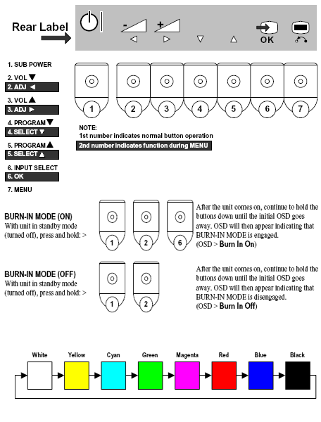
BURN-IN MODE
When the Burn-in feature is turned ON, the plasma panel operates normally on all inputs that have a signal. On inputs that do not have a signal, the plasma panel displays a cycling single color test pattern (see below) which is generated internally. This can be helpful to determine if the panel is capable of displaying anything.

DEMO MODE
When the DEMO feature is turned ON, both the remote and the plasma panel front panel
buttons (with the exception of the SUB POWER button) are non-operational. This can be
useful for the Sales / Dealers to prevent anyone from playing with any of the settings.
NOTE: This is the front panel shortcut to parameter #175 in the I2C ADJUSTMENT MODE.

SERVICE MODE ACCESS
I2C ADJUSTMENT MODE
When the set is in the I2C Adjustment mode, use the cursor buttons for selecting the
adjustment parameter, and for changing the parameter’s value. Use the OK button to
confirm. After adjustments are complete, press the MENU button to return the set to normal
operating condition.
MEMORY INITIALIZATION
Don’t indiscriminately perform this procedure as it can result in a loss of data if the old values were not recorded.
1. Engage I2C Adjustment mode.
2. Select parameter #744. Change the data value from “0” to “1”.
3. Activate MEMORY INITIALIZATION by holding down the OK button for at least three seconds.
4. Select parameter #374. Change the data value from “1” to “0”.
5. Check that the set changes input to AV1, indicating that the preset values have been loaded.
SERVICE MODE ACCESS
FACTORY RESET
Occasionally, it becomes necessary to perform a factory reset. This is different than the
Memory Initialization, only customer settings are affected by Factory Reset.
SERVICE MODE ACCESS
DIAGNOSIS MODE
This chassis has a limited self-diagnosis mode. When activated, the microprocessor generates a series
of internal communication checks and outputs the results via OSD, as seen on the table below. Since
it uses the OSD to display the results, any circuit failures which result in a “no display” or “no picture”
condition will not be able to be seen, obviously. ANY operation (volume, channel, menu, input,
etc.) will cause the unit to exit from the Diagnosis mode.

Hitachi 42EDT41 TV Service Menu (All TV Service Menu Code)
5
stars -
"Hitachi 42EDT41 TV Service Menu"
by Admin 2
Hitachi 42EDT41 TV Service Menu mode, Hitachi 42EDT41 factory mode Written on June 07, 2015


 You are reading Hitachi 42EDT41 TV Service Menu.