All TV Service Menu Code

Electronic Repair, Manuals, Reference and TV Factory service mode

  • Home
  • Database
  • LCD
  • LED
  • CRT
  • Plasma
  • DLP
  • FORUM
  • Upload
  • Download
  • Join
  • Rss
  • Mobile
  • Elite 21ES02 TV Service Menu
  • Nokia A
  • Grundig TV Hotel mode
  • Grundig Chassis 22.1 TV Service menu
  • Grundig Chassis D6 TV Service menu
  • Hisense TV Service Menu
  • Panasonic TV Service Menu
  • Brandt 70172 TV Service Menu
  • Akira TV CT29XG9A TV Service menu
  • Thomson TX-90 CTV Service menu

Sansui 3200D TV Service Menu

Sansui | Author | April 19, 2020

SANSUI HD LCD 3200D TV Service menu mode

32" WIDE TFT LCD TELEVISION
WITH DIGITAL TUNER

Operating the receiver outside of its cabinet or with its back removed involves a shock hazard. Work on these models should only be performed by those who are thoroughly familiar with precautions necessary when working on high voltage equipment.
Exercise care when servicing this chassis with power applied. Many B plus and high voltage RF terminals are exposed which, if carelessly contacted, can cause serious shock or result in damage to the chassis.
Maintain interconnecting ground lead connections between chassis, escutcheon, picture tube dag and
tuner cluster when operating the chassis These receivers have a "polarized" AC line cord. The AC
plug is designed to fit into standard AC outlets in one direction only. The wide blade connects to the "ground side" and the narrow blade connects to the "hot side" of the AC line. This assures that the TV receiver is properly grounded to the house wiring. If an extension cord must be used, make sure it is of the "polarized" type.
Since the chassis of this receiver is connected to one side of the AC supply during operation, service should not be attempted by anyone not familiar with the precautions necessary when working on these types of equipment When it is necessary to make measurements or tests with
AC power applied to the receiver chassis, an Isolation Transformer must be used as a safety precaution and to prevent possible damage to transistors. The Isolation Transformer should be connected between the TV line cord plug and the AC power outlet.
When removing springs or spring mounted parts from the tuner, tuner cluster or chassis, shatterproof goggles must be worn. Keep others without shatterproof goggles away.
Before returning the receiver to the user, perform the following safety checks:
1 Inspect all lead dress to make certain that leads are not pinched or thai hardware is not lodged between the chassis and other metal parts in the receiver
2 Replace all protective devices such as nonmeiallic control knobs, Insulating fishpapers. cabinet backs adjustment and compartment covers or shields, isolation resistor-capacitor networks, mechanical Insulators, etc
3 To be sure that no shock hazard exists, a check for the presence of leakage current should be made at each exposed metal part having a return path to the chassis (antenna, cabinet metal, screw heads,
knobs and-'or shafts, escutcheon, etc ) In the following manner Mug the AC line cord directly into a 120V AC receptacle.
(Do not use an Isolation Transformer dunng these checks) All checks must be repeated with the AC line record plug connection reversed, (if necessary, anonpolarized adapter plug must be used only for the purpose of completing these checks.)
If available, measure current using an accurate leakage current (ester Any reading of 0 35mA or more is excessive and indicates a potential shock hazard which must be corrected before returning the receiver to the owner If a reliable leakage current tester is not available, this alternate method of measurement should be used Using two clip leads, connect a 1500 ohm. 10 watt resistor paralleled by a 0.15uF capacitor in series with a known earth ground, such as a water pipe or conduit and the metal part to be checked Use a VTVM or VOM with 1000 ohms pe* volt, or higher, sensitivity to rne.-.F.!.-* 1 hi f- AC vc la^f. d'op .=cross :ie re&is:or Ary readmg of 035 volt RMS or more is excessive and Indicates a potential shock hazard which must be corrected before returning the receiver to the owner

Sansui HDLCD3200D TV Service Menu


WHEN REPLACING EEPROM (MEMORY) IC Sansui HDLCD3200D
CONFIRMATION OF CHECK SUM, POWER ON TOTAL HOURS AND MICON VERSION
Initial total of MEMORY IC. POWER ON total hours and MICON VERSION can be checked on the screen. Total houis are
displayed in 16 system of notation
NOTE: If you set a factory Initialization, the total hours Is reset to "0".
Please refer to 'CONFIRMATION OF INITIAL DATA" when SUM DATA is not corresponding.
1. Turn on the POWER, and set to the TV mode
2 Set the VOLUME to minimum.
3. Press both VOL DOWN button on the set and Channel button (8) on the remote control for more than 2 seconds.
4 After the confirmation of each check sum. turn off the power
NOTE The each item value might be different according to each set|

CONFIRMATION OF INITIAL DATA
If a service repair is undertaken where it has been required to change the MEMORY IC, the following steps should be
taken to ensure correct data settings while making reference to INITIAL SETTING TABLE (Attached "INITIAL DATA").
1. Turn on the POWER, and set to the TV mode
2. Set the VOLUME to minimum.
3   Press both VOL DOWN button on the set and Channel button (6) on the remote control for more than 2 seconds
4 ADDRESS is now selected and should "blink" Using Ihe UP/DOWN buton on the remote, step through the ADDRESS
until required ADDRESS to be changed is reached.
5 Press LEFT/RIGHT button to select DATA When DATA -s selected. It will "blink".
6. Again, step through the DATA using UP/DOWN button until required DATA value has been selected
7 Pressing LEFT/RIGHT button will take you back to ADDRESS lor further selection if necessary
8 Repeat steps 4 to 6 until all data has been checked
9. When satisfied correct DATA has been entered, turn POWER off (return to STANDBY MODE) to finish DATA input.
After the data input, set to the initializing of shipping.
10 Turn on the POWER, and set to the TV mode.
11 Press both VOL. DOWN button on the set and Channel button (1) on Ihe remote control for more than 2 seconds
12. After the finishing of the initializing of shipping, the unit will turn off automatically
The unit will now have the correct DATA for the new MEMORY IC.


Sansui 1909 TV Service Menu

Sansui | Author | April 18, 2020

SERVICE MODE SANSUI HD LCD 1909

ORIGINAL CODE NO. M39A05WASM
19" WIDE TFT LCD TELEVISION WITH DIGITAL TUNER
VERSION (B) DATE OF ISSUE 8/2009 All the
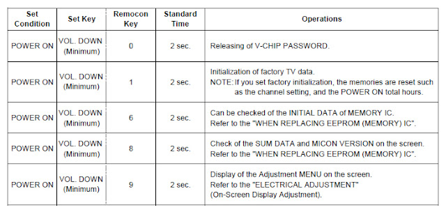
Tfi is unit is provided with the following SERVICE MODES so you can repair, examine and adjust easily.
To enter to the SERVICE MODE function, press and hold both buttons simultaneously on the main unit and on the remote
control for more than a the standard time in the appropriate condition. (See below chart.)

Set Condition    Set Key    Remocon Key    Standard Time    Operations
POWER ON    VOL. DOWN (Minimum)    0    2 sec.    Releasing of V-CHIP PASSWORD.
POWER ON    VOL. DOWN (Minimum)    i 1    2 sec.    Initialization of factory TV data. NOTE: if you set factory initialization, the memories are reset such as the channel setting, and the POWER ON total hours.
POWER ON    VOL. DOWN (Minimum)    i 6    2 sec.    Can be checked of the INITIAL DATA of MEMORY IC Refer to the "WHEN REPLACING EEPROM (MEMORY) IC".
POWER ON    VOL. DOWN (Minimum)    i i i 8    2 sec.    Check of the SUM DATA and MICON VERSION on the screen. Refer to the "WHEN REPLACING EEPROM (MEMORY) IC".
POWER ON    VOL. DOWN (Minimum)    I i 9 i    2 sec.    Display of the Adjustment MENU on the screen. Refer to the "ELECTRICAL ADJUSTMENT (On-Screen Display Adjustment).


SANSUI HDLCD1909 TV Service Menu


WHEN REPLACING EEPROM (MEMORY) IC SANSUI HD LCD 1909 TV
CONFIRMATION OF CHECK SUM, POWER ON TOTAL HOURS AND MICON VERSION
Initial total of MEMORY IC, POWER ON total hours and MICON VERSION can be checked on the screen. Total hours are displayed in 16 system of notation.
NOTE: If you set a factory initialization, the total hours is reset to "0".
Please refer to "CONFIRMATION OF INITIAL DATA" when SUM DATA is not corresponding.
1. Turn on the POWER, and set to the ALL mode.
2. Set the VOLUME to minimum.
3. Press both VOL. DOWN button on the set and Channel button (8) on the remote control for more than 2 seconds.
4. After the confirmation of each check sum, turn off the power.
NOTE: The each item value might be different according to each set.

CONFIRMATION OF INITIAL DATA SANSUI HDLCD1909 TV
If a service repair is undertaken where it has been required to change the MEMORY IC, the following steps should be taken to ensure correct data settings while making reference to INITIAL SETTING TABLE (Attached "INITIAL DATA").
1. Turn on the POWER, and set to the ALL mode.
2. Set the VOLUME to minimum.
3. Press both VOL. DOWN button on the set and Channel button (6) on the remote control for more than 2 seconds.
ADDRESS and DATA should appear
NOTE: No need to set data other position than 0D00~0EFF.
4. ADDRESS is now selected and should "blink". Using the CH. UP/DOWN buton on the remote, step through the ADDRESS
until required ADDRESS to be changed is reached.
5. Press VOL. UP/DOWN button to select DATA. When DATA is selected, it will "blink".
6. Again, step through the DATA using CH. UP/DOWN button until required DATA value has been selected.
7. Pressing VOL. UP/DOWN button will take you back to ADDRESS for further selection if necessary.
8. Repeat steps 4 to 6 until all data has been checked.
9. When satisfied correct DATA has been entered, turn POWER off (return to STANDBY MODE) to finish DATA input After the data input, set to the initializing of shipping.
10. Turn on the Power.
11. Set the VOLUME to minimum.
12. Press both VOL. DOWN button on the set and Channel button (1) on the remote control for more than 2 seconds.
13. After the finishing of the initializing of shipping, the unit will turn off automatically.
The unit will now have the correct DATA for the new MEMORY IC.

ELECTRICAL ADJUSTMENTS SANSUI HD LCD 1909 TV
1. ADJUSTMENT PROCEDURE
Read and perform these adjustments when repairing the circuits or replacing electrical parts or PCB assemblies.
CAUTION
• Use an isolation transformer when performing any service on this chassis.
• When removing a PCB or related component, after unfastening or changing a wire, be sure to put the wire back in its original position.
• When you exchange IC and Transistor with a heat sink, apply silicon grease(YG6260M) on the contact section of the heat sink. Before applying new silicon grease, remove all the old silicon grease. (Old grease may cause damage to the IC and Transistor).
Prepare the following measurement tools for electrical adjustments.
1. Pattern Generator On-Screen Display Adjustment
1. Set the VOLUME to minimum.
2. Press the VOL. DOWN button on the set and the channel button (9) on the remote control for more than 2 seconds to display adjustment mode on the screen
3. Use the CH UP/DOWN button or Channel button (0-9) on the remote control to select the options 4. Press the MENU button on the remote control to end the adjustments.
5. To display the adjustment screen for TV, AV.COMPONENT HDMI and PC mode, press the INPUT SELECT button on the remote control.
6. Receive the DIGITAL broadcasting.
7. To display the adjustment screen fo DTV mode, select the digital channel.
8. Press the VOL.DOWN buttom on the set and the channel
(9) on the remote control for more than 2 seconds.

NO.    FUNCTION    NO.    FUNCTION
C3    R DRIVE(N)    34    BRIGHTNESS MIN
04    R CUTOFF(N)    35    TINT
05    G DRIVE(N)    36    SHARP H1 MAX
06    G CUTOFF(N)    37    SHARP H1 MIN
C7    8 DRIVE(N)    38    SHARP H2 MAX
C8    B CUTOFF(N)    39    SHARP H2 MIN
C9    R DRIVE(C)    40    SHARP H3 MAX
10    R CUTOFF(C)    41    SHARP H3 MIN
11    G DRIVE(C)    42    SHARP H4 MAX
12    G CUTOFF(C)    43    SHARP H4 MIN
13    B DRIVE(C)    44    SHARP H5 MAX
14    B CUTOFF(C)    46    SHARP H5 MIN
15    R DRIVE(W)    46    SHARP V1 MAX
16    R CUTOFF(W)    47    SHARP V1 MIN
'7    G DRIVE(W)    46    SHARP V2 MAX
ia    G CUTOFF(W)    49    SHARP V2 MIN
19    B DRIVE(W)    50    CONTRAST CENTER
20    B CUTOFF(W)    51    CONTRAST MAX
29    BAK LIGHT CENT    52    CONTRAST MIN
30    BAK LIGHT MAX    53    COLOR CENTER
31    BAK LIGHT MIN    54    COLOR MAX
33    BRIGHTNESS CENT    55    COLOR MIN
33    BRIGHTNESS MAX    58    CONTRAST 40

2. BASIC ADJUSTMENTS SANSUI HD LCD 1909 TV
2-1: WHITE BALANCE SANSUI HD LCD 1909 TV
1. Place the set in Aging Test for more than 30 minutes.
2. Receive the gray scale pattern from the Pattern Generator.
3. Press the INPUT SELECT button on the remote control to set to the AV mode.
4. Using the remote control, set the brightness and contrast to normal position.
5. Activate the adjustment mode and press the channel button (03) on the remote control to
selecf'R DRIVE (N)".
6. Press the UP/DOWN button on the remote control to select the "R CUTOFF (N)", "G DRIVE (N)",
G CUTOFF (N), "B DRIVE (N)", "B CUTOFF (N)",
R DRIVE (C), "R CUTOFF (C)", "G DRIVE (C)",
G CUTOFF (C), "B DRIVE (C)", "B CUTOFF (C)",
R DRIVE (W), "R CUTOFF (W)", "G DRIVE (W)",
G CUTOFF (W), "B DRIVE (W)" or "B CUTOFF (W)".
7. Adjust the LEF/RIGHT button on the remote control to whiten the R CUTOFF (N), G DRIVE (N),
G CUTOFF (N), B DRIVE (N), B CUTOFF (N),
R DRIVE (C), R CUTOFF (C), G DRIVE (C),
G CUTOFF (C), B DRIVE (C), B CUTOFF (C),
R DRIVE (W), R CUTOFF (W), G DRIVE (W),
G CUTOFF (W), B DRIVE (W) and B CUTOFF (W) at each step tone sections equally.
8. Perform the above adjustments 6 and 7 until the white color is achieved.


Sansui TVS-273 TV Service menu

Sansui | Author | April 14, 2015
Sansui TVS-273 TV Service mode
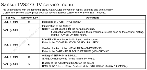
How to enter to Sansui TVS-273 factory menu mode?.. Bellow the step by step to enter the factory mode. Please remember to write down all original data before make any change to service menu data. Wrong settings will cause a serious damage to your television, your own risk to enter service menu mode.
TV Service menu Sansui TVS-273

Sansui TVS-273 TV Service menu


CONFIRMATION OF HOURS USED
POWER ON total hours can be checked on the screen. Total hours are displayed in 16 system of notation.
NOTE: If you set a factory initialization, the total hours is reset to "0".
Set the VOLUME to minimum.
Press both VOL. DOWN button on the set and Channel button (6) on the remote control for more than 1 second.
After the confirmation of using hours, turn off the power.

The unit will now have the correct DATA for the new MEMORY IC.
Enter DATA SET mode by setting VOLUME to minimum.
Press both VOL. DOWN button on the set and Channel button (6) on the remote control for more than 1 second.

ADDRESS is now selected and should "blink". Using the VOL. UP/DOWN button on the remote, step through the ADDRESS until required ADDRESS to be changed is reached.
Press ENTER to select DATA. When DATA is selected, it will "blink".
Again, step through the DATA using VOL. UP/DOWN button until required DATA value has been selected.
Pressing ENTER will take you back to ADDRESS for further selection if necessary.
Repeat steps 3 to 6 until all data has been checked.
When satisfied correct DATA has been entered, turn POWER off (return to STANDBY MODE) to finish DATA input.
After the data input, set to the initializing of shipping.
Turn POWER on.
Press both VOL. DOWN button on the set and Channel button (1) on the remote control for more than 1 second. After the finishing of the initializing of shipping, the unit will turn off automatically.
1. ADJUSTMENT PROCEDURE Sansui TVS-273 TV Service mode
Read and perform these adjustments when repairing the circuits or replacing electrical parts or PCB assemblies.
CAUTION
Use an isolation transformer when performing any service on this chassis.
Before removing the anode cap, discharge electricity because it contains high voltage.
When removing a PCB or related component, after unfastening or changing a wire, be sure to put the wire back in its original position.
When you exchange IC and Transistor for a heat sink, apply the silicon grease on the contact section of the heat sink. Before applying new silicon grease, remove all the old silicon grease. (Old grease may cause damages to the IC and Transistor.)

Prepare the following measurement tools for electrical
adjustments.
1. Oscilloscope
2. Digital Voltmeter
3. Multi-sound Generator
4. Pattern Generator
On-Screen Display Adjustment
1. In the condition of NO indication on the screen.
Press the VOL. DOWN button on the set and the Channel button (9) on the remote control for more than 1 second to appear the adjustment mode on the screen as shown in.

CONSTANT VOLTAGE
Place the set with Aging Test for more than 5 minutes.
Set condition is AV MODE without signal.
Connect the digital voltmeter to the TP003.
Adjust the VR502 until the digital voltmeter is 135 ± 0.5V.

CUT OFF
Place the set with Aging Test for more than 15 minutes.
Activate the adjustment mode display of Fig. 1-1 and press the channel button (01) on the remote control to select "CUT OFF".
Adjust the Screen Volume until a dim raster is obtained.


Sansui TVS-273 TV Service mode WHITE BALANCE
NOTE: Adjust after performing CUT OFF adjustment.
Place the set with Aging Test for more than 10 minutes.
Receive the gray scale pattern from the Pattern Generator.
Using the remote control, set the brightness and contrast to normal position.
Activate the adjustment mode and press the channel button (12) on the remote control to select “R. BIAS”.
Press the CH. UP/DOWN button on the remote control to select the “R. BIAS”, “G. BIAS”, “B. BIAS”, “B. DRIVE” or
“G. DRIVE”.
Adjust the VOL. UP/DOWN button on the remote control to whiten the R. BIAS, G. BIAS, B. BIAS, B. DRIVE, and
G. DRIVE at each step tone sections equally.
Perform the above adjustments 5 and 6 until the white color is looked like a white.

FOCUS
Receive the monoscope pattern.
Turn the Focus Volume fully counterclockwise once.
Adjust the Focus Volume until picture is distinct.

HORIZONTAL PHASE
Receive the monoscope pattern.
Using the remote control, set the brightness and contrast to normal position.
Activate the adjustment mode  and press the channel button (03) on the remote control to select “H. PHAS”.
Press the VOL. UP/DOWN button on the remote control until the SHIFT quantity of the OVER SCAN on right and left becomes minimum.

HORIZONTAL SIZE
Receive the monoscope pattern.
Using the remote control, set the brightness and contrast to normal position.
Activate the adjustment mode display and press the channel button (06) on the remote control to select “H. SIZE”.
Press the VOL. UP/DOWN button on the remote control until the SHIFT quantity of the OVER SCAN on right and left becomes 10%

VERTICAL POSITION
Receive the monoscope pattern.
Using the remote control, set the brightness and contrast to normal position.
Adjust the VR401 until the horizontal line becomes fit to the notch of the shadow mask.

VERTICAL SIZE
Receive the monoscope pattern.
Using the remote control, set the brightness and contrast to normal position.
Activate the adjustment mode display  and press the channel button (07) on the remote control to select “V. SIZE”.
Press the VOL. UP/DOWN button on the remote control until the SHIFT quantity of the OVER SCAN on upside and downside becomes 9 ± 2%.

VERTICAL LINEARITY
NOTE: Adjust after performing adjustments in section 2-8.
After the adjustment of Vertical Linearity, reconfirm the Vertical Position and Vertical Size adjustments.
Receive the monoscope pattern.
Using the remote control, set the brightness and contrast to normal position.
Activate the adjustment mode display  and press the channel button (08) on the remote control to select “V. LIN”.
Press the VOL. UP/DOWN button on the remote control until the SHIFT quantity of the OVER SCAN on upside and downside becomes minimum.

LEVEL
Receive the VHF HIGH (70dB).
Connect the AC voltmeter to pin 6 of CP101.
Activate the adjustment mode display  and press the channel button (33) on the remote control to select "LEVEL".
Press the VOL. UP/DOWN button on the remote control until the AC voltmeter is 75 ± 2mV.

CORNER
Receive the crosshatch signal from the Pattern Generator.
Using the remote control, set the brightness and contrast to normal position.
Activate the adjustment mode display  and press the channel button (31) on the remote control to select “CORNER”.
Press the VOL. UP/DOWN button on the remote control until the right and left vertical lines are straight.

TRAPEZIUM
Receive the crosshatch signal from the Pattern Generator.
Using the remote control, set the brightness and contrast to normal position.
Activate the adjustment mode display and press the channel button (32) on the remote control to select “TRAPEZIUM”.
Press the VOL. UP/DOWN button on the remote control until the both vertical lines of the screen become parallel.

SEPARATION 1, 2
Set the multi-sound signal generator for each different L-ch and R-ch frequency (Ex. L-ch=2KHz, R-ch=400Hz)
and receive the RF.
Connect the oscilloscope to the Audio Out Jack.
Activate the adjustment mode display and press the channel button (34) on the remote control to select “SEP 1”.
Press the VOL. UP/DOWN button on the remote control to adjust it until the audio output wave becomes a fine sine wave.
Press the CH UP button once the set to "SEP 2" mode.
Then perform the above adjustment
Method (1)
Set the multi-sound signal generator L-ch=1KHz, R-ch =Non input and receive the RF.
Connect the oscilloscope to the Audio Out Jack (R-ch).
Press the AUDIO SELECT button on the remote control to set to the stereo mode.
Activate the adjustment mode display  and press the channel button (34) on the remote control to select “SEP 1”.
Press the VOL. UP/DOWN button on the remote control to adjust it until the R-ch output becomes minimum.
Set the multi-sound signal generator L-ch=Non input, R-ch=1KHz and receive the RF.
Connect the oscilloscope to the Audio Out Jack (L-ch).
Activate the adjustment mode display  and press the channel button (35) on the remote control to select “SEP 2”.
Press the VOL. UP/DOWN button on the remote control to adjust it until the L-ch output becomes minimum.

Method (2)
Please do the method (1) or method (2) adjustment.
BRIGHT CENT
Receive the monoscope pattern. (RF Input)
Using the remote control, set the brightness and contrast to normal position.
Activate the adjustment mode display and press the channel button (16) on the remote control to select "BRI CENT".
Press the VOL. UP/DOWN button on the remote control until the white 0% is starting to be visible
Receive the monoscope pattern. (Audio Video Input)
Press the TV/VIDEO button on the remote control to set to the AV mode. Then perform the above adjustments 2~4.
Press the TV/VIDEO button on the remote control to set to the CS mode.
Activate the adjustment mode display and press the channel button (16) on the remote control to select "BRI CENT".
Press the VOL. UP/DOWN button on the remote control until the brightness step No. becomes “90”.

TINT/COLOR CENT
Receive the color bar pattern.
Connect the oscilloscope to TP806.
Activate the adjustment mode display and press the channel button (24) on the remote control to select "TINT".
Press the VOL. UP/DOWN button on the remote control until the section "A" becomes as straight line Connect the oscilloscope to TP804.
Activate the adjustment mode display and press the channel button (22) on the remote control to select "COL.CENT".
Press the VOL. UP/DOWN button on the remote control until the red color level is adjusted to 120 ± 10% of the white level.
Receive the color bar pattern. (Audio Video Input)
Press the TV/VIDEO button on the remote control to set to the AV mode. Then perform the above adjustments 2~7.
Press the TV/VIDEO button on the remote control to set to the CS mode.
Press the VOL. UP/DOWN button on the remote control to set the same step numbers as the AV mode.

Sansui TVS-273 TV Service mode CONTRAST MAX MANUAL
Activate the adjustment mode display and press the channel button (18) on the remote control to select “CONT. MAX”.
Press the VOL. UP/DOWN button on the remote control until the contrast step No. becomes “100”.
Receive a broadcast and check if the picture is normal.
Press the TV/VIDEO button on the remote control to set to the AV mode. Then perform the above adjustments 1~3.
Press the TV/VIDEO button on the remote control to set to the CS mode. Then perform the above adjustments 1~3.

2-15: TINT/COLOR CENT
Receive the color bar pattern.
Connect the oscilloscope to TP806.
Activate the adjustment mode display and press the channel button (24) on the remote control to select "TINT".
Press the VOL. UP/DOWN button on the remote control until the section "A" becomes as straight line Connect the oscilloscope to TP804.
Activate the adjustment mode display and press the channel button (22) on the remote control to select "COL.CENT".
Press the VOL. UP/DOWN button on the remote control until the red color level is adjusted to 120 ± 10% of the white level.
Receive the color bar pattern. (Audio Video Input)
Press the TV/VIDEO button on the remote control to set to the AV mode. Then perform the above adjustments 2~7.
Press the TV/VIDEO button on the remote control to set to the CS mode.
Press the VOL. UP/DOWN button on the remote control to set the same step numbers as the AV mode.
white 100% red 120%
2-17: OSD HORIZONTAL
Activate the adjustment mode display
Press the VOL. UP/DOWN button on the remote control until the difference of A and B becomes minimum.

PURITY AND CONVERGENCE
Sansui TVS-273 TV Service mode ADJUSTMENTSNOTE
Turn the unit on and let it warm up for at least 30 minutes before performing the following adjustments.
Place the CRT surface facing east or west to reduce the terrestrial magnetism.
Turn ON the unit and demagnetize with a Degauss Coil.

3-1: STATIC CONVERGENCE (ROUGH ADJUSTMENT)
Tighten the screw for the magnet. Refer to the adjusted CRT for the position.
If the deflection yoke and magnet are in one body, untighten the screw for the body.
Receive the green raster pattern from the color bar generator.
Slide the deflection yoke until it touches the funnel side of the CRT.
Adjust center of screen to green, with red and blue on the sides, using the pair of purity magnets.
Switch the color bar generator from the green raster pattern to the crosshatch pattern.
Combine red and blue of the 3 color crosshatch pattern on the center of the screen by adjusting the pair of 4 pole magnets.
Combine red/blue (magenta) and green by adjusting the pair of 6 pole magnets.
Adjust the crosshatch pattern to change to white by repeating steps 6 and 7.

PURITY NOTE
Adjust after performing adjustments in section 3-1.
Receive the green raster pattern from color bar generator.
Adjust the pair of purity magnets to center the color on the screen.
Adjust the pair of purity magnets so the color at the ends are equally wide.
Move the deflection yoke backward (to neck side)
slowly, and stop it at the position when the whole screen is green.
Confirm red and blue color.
Adjust the slant of the deflection yoke while watching the screen, then tighten the fixing screw.

STATIC CONVERGENCE
NOTE
Adjust after performing adjustments in section 3-2.
Receive the crosshatch pattern from the color bar generator.
Combine red and blue of the 3 color crosshatch pattern on the center of the screen by adjusting the pair of 4 pole magnets.
Combine red/blue (magenta) and green by adjusting the pair of 6 pole magnets.

3-4: DYNAMIC CONVERGENCE
NOTE
Adjust after performing adjustments in section 3-3.
Adjust the differences around the screen by moving the deflection yoke upward/downward and right/left. Insert three wedges between the deflection yoke and CRT funnel to fix the deflection yoke.


Sansui TV Service Menu

Sansui | Author | September 28, 2009
Sansui TV Service Menu
With the Sansui TV turned on without OSD, press the remote control of Sansui television, via the hidden key a small hole in it (If you do not have the hole, disarm remote control and find the key that is not accessible externally)(Sansui). The sub menus and items are selected with the corresponding number. The values are adjusted with volume +/- , to exit and save, press 0 key.
or
Sansui TV Service Menu, Press menu button on the remote control , channel down, enter the code as a password 1947 to open factory mode.

Photo credit to www.wotif.com


Universal Remote

  • Chunghop RM-168GS code List
  • iWave Supersize Universal Remote
  • Automator URC 200 CD Players
  • Asaki Universal Remote for DVD
  • AMAZONE Universal Remote for DVD

CRT Television

  • Zenit TV Service Menu
  • Hisense HSM 515AV TV Service Menu
  • Grundig CUC 7301 TV Service menu
  • SIERA SG1420 TV Service Menu
  • RCA G27684 TV Service Menu


Plasma Television

  • Samsung HCH 551WX TV Service Menu
  • Beko L5C TFT LCD TV Service Menu
  • Beko LCD PLASMA L6E TV Service Menu
  • Beko Plasma TV Service Menu
  • Samsung Plasma TV Service Menu

LED Television

  • How to enter to Sansui TV Service Menu
  • LG 42LB62 LED TV Service Menu
  • Sanyo LED LCD TV Service Menu
  • How to enter to Telefunken TV Service Menu
  • Konka LED TV Service Menu

LCD Television

  • Hisense LCD 19V87 TV Service menu
  • Insignia NS LCD37HD-09 TV Service menu
  • Hisense K15 Series TV Service Menu
  • Hisense MT5380 TV Service menu
  • Grundig 42PX TV Service Menu


  • FORUM
  • Announce
  • Claim
  • Contributor
  • Universal Remote
  • Terms of Service
  • Privacy Policy
  • About
  • Contact
© 2008 - tvservicemenu. All Rights Reserved