All TV Service Menu Code

Electronic Repair, Manuals, Reference and TV Factory service mode

  • Home
  • Database
  • LCD
  • LED
  • CRT
  • Plasma
  • DLP
  • FORUM
  • Upload
  • Download
  • Join
  • Rss
  • Mobile
  • Grundig TV Hotel mode
  • Grundig Chassis 22.1 TV Service menu
  • Grundig Chassis D6 TV Service menu
  • Panasonic TX-15LT2Z TV Service menu
  • CRT TV Service Mode List
  • Siera SG1420 TV Service Menu
  • Grundig CUC 7301 TV Service menu
  • Chunghop RM-168GS code List
  • Hitachi 42HDT50 TV Service Menu
  • How to enter to Sansui TV Service Menu

LG 42LK450-UB TV Service Menu

LG / LGein | Author | April 20, 2020

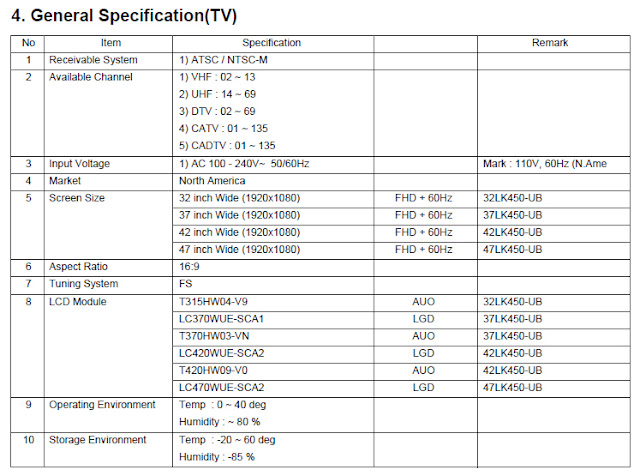
SPECIFICATION LG 42LK450-UB TV LCD
NOTE : Specifications and others are subject to change without notice for improvement.

#1. Application range
This spec sheet is applied LCD TV with 32”, 37”, 42”, 47”, 55”
LA01U chassis.
#2. Requirement for Test
Each part is tested as below without special appointment.
1) Temperature: 25 ºC ± 5 ºC
2) Relative Humidity: 65 ± 10 %
3) Power Voltage : Standard input voltage(100-240V~, 50/60Hz)
* Standard Voltage of each product is marked by models
4) Specification and performance of each parts are followed
each drawing and specification by part number in
accordance with BOM.
5) The receiver must be operated for about 5 minutes prior to
the adjustment.

#3. Test method
1) Performance: LGE TV test method followed
2) Demanded other specification
- Safety : UL, CSA, IEC specification
- EMC: FCC, ICES, IEC specification

LG 42LK450-UB TV factory mode

LG 42LK450-UB TV Service Menu


LG 42LK450-UB TV Service Menu
1. Application range LG 42LK450-UB
This spec. sheet applies to LA01U Chassis applied LED LCD
TV all models manufactured in TV factory.

2. Specification
2.1 Because this is not a hot chassis, it is not necessary to use an isolation transformer. However, the use of isolation transformer will help protect test instrument.
2.2 Adjustment must be done in the correct order.
2.3 The adjustment must be performed in the circumstance of 25±5°C of temperature and 65±10% of relative humidity 2.4 The input voltage of the receiver must keep 100~240V~, 50/60Hz.
2.5 At first Worker must turn on the SET by using Power Only key.
2.5 The receiver must be operated for about 5 minutes prior to the adjustment when module is in the
circumstance of over 15.
In case of keeping module is in the circumstance of 0°C, it should be placed in the circumstance of above 15°C for 2 hours In case of keeping module is in the circumstance of below -20°C, it should be placed in the circumstance of above 15°C for 3 hours.
• Caution
When a still image is displayed for 20 minutes or longer (especially where W/B scale is strong. Digital pattern 13ch and/or Cross hatch pattern 09ch), there can some afterimage in the black level area.

3. Adjustment items LG 42LK450-UB TV Service Menu
3.1 Board Level Adjustment
(1) Adjust 480i Comp1(ADC)
(2) EDID/DDC download
• Remark
- Above adjustment items can be also performed in Final Assembly if needed. Adjustment items in both PCBA and final assembly stages can be checked by using the INSTART Menu 1.ADJUST CHECK.
3.2 Final Assembly adjustment
(1) White Balance adjustment
(2) RS-232C functionality check
(3) Factory Option setting per destination
(4) Shipment mode setting (IN-STOP)
3.3 Etc
(1) Ship-out mode
(2) Service Option Default
(3) USB Download(S/W Update, Option, Service only)
(4) ISP Download (Optional)

4. Board Level Adjustment LG 42LK450-UB TV Service Menu
4.1. ADC Adjustment
4.1.1. Overview
• ADC adjustment is needed to find the optimum black level and gain in Analog-to-Digital device and to compensate RGB deviation.
4.1.2. Equipment & Condition
1) Jig (RS-232C protocol)
• Required equipment : Adjustment R/C
*Enter Service Mode by pushing “ADJ” key,
*Enter Internal ADC mode by pushing “G” key at “6. ADC
Calibration”
4.1.3. Adjustment
4.1.3.1 Adjustment method
• Using RS-232, adjust items listed in 3.1 in the other shown in “4.1.3.3”
3. Adjustment items
3.1 Board Level Adjustment
(1) Adjust 480i Comp1(ADC)
(2) EDID/DDC download
• Remark
- Above adjustment items can be also performed in Final
Assembly if needed. Adjustment items in both PCBA and
final assembly stages can be checked by using the INSTART Menu 1.ADJUST CHECK.
3.2 Final Assembly adjustment
(1) White Balance adjustment
(2) RS-232C functionality check
(3) Factory Option setting per destination
(4) Shipment mode setting (IN-STOP)
3.3 Etc
(1) Ship-out mode
(2) Service Option Default
(3) USB Download(S/W Update, Option, Service only)
(4) ISP Download (Optional)


LG LED 55LW980S-ZA TV Service menu

LG / LGein | Author | April 15, 2020
LG LED mode55LW980S-ZA TV Service menu CHASSIS : LD12D
LG LED 55LW980S-ZA TV Service menu General Guidance
An isolation Transformer should always be used during the servicing of a receiver whose chassis is not isolated from the AC power line. Use a transformer of adequate power rating as this protects the technician from accidents resulting in personal injury from electrical shocks.
It will also protect the receiver and it's components from being damaged by accidental shorts of the circuitry that may be inadvertently introduced during the service operation.
If any fuse (or Fusible Resistor) in this TV receiver is blown, replace it with the specified.
When replacing a high wattage resistor (Oxide Metal Film Resistor, over 1 W), keep the resistor 10 mm away from PCB.
Keep wires away from high voltage or high temperature parts.
Before returning the receiver to the customer, always perform an AC leakage current check on the exposed metallic parts of the cabinet, such as antennas, terminals, etc., to be sure the set is safe to operate without damage of electrical shock.
Leakage Current Cold Check(Antenna Cold Check)
With the instrument AC plug removed from AC source, connect an electrical jumper across the two AC plug prongs. Place the AC switch in the on position, connect one lead of ohm-meter to the AC
plug prongs tied together and touch other ohm-meter lead in turn to each exposed metallic parts such as antenna terminals, phone jacks, etc.
If the exposed metallic part has a return path to the chassis, the measured resistance should be between 1 MΩ and 5.2 MΩ.
When the exposed metal has no return path to the chassis the reading must be infinite.
An other abnormality exists that must be corrected before the receiver is returned to the customer.

Leakage Current Hot Check (See below Figure)
Plug the AC cord directly into the AC outlet.
Do not use a line Isolation Transformer during this check.
Connect 1.5 K / 10 watt resistor in parallel with a 0.15 uF capacitor between a known good earth ground (Water Pipe, Conduit, etc.)
and the exposed metallic parts.
Measure the AC voltage across the resistor using AC voltmeter with 1000 ohms/volt or more sensitivity.
Reverse plug the AC cord into the AC outlet and repeat AC voltage measurements for each exposed metallic part. Any voltage measured must not exceed 0.75 volt RMS which is corresponds to 0.5 mA.
In case any measurement is out of the limits specified, there is possibility of shock hazard and the set must be checked and repaired before it is returned to the customer.
Leakage Current Hot Check circuit


LG LED 55LW980S-ZA TV Service menu


3. Automatic Adjustment
3.1. ADC Adjustment
(1) Overview
ADC adjustment is needed to find the optimum black level and gain in Analog-to-Digital device and to compensate RGB deviation.
* If Adjust ADC is “OTP”, It doesn’t need ADC adjustment.
(GP3-BCM)
(2) Equipment & Condition
1) Jig (RS-232C protocol)
2) MSPG-925 Series Pattern Generator(MSPG-925FA, pattern - 65)
- Resolution : 480i Comp1 1080P Comp1 1920*1080 RGB
- Pattern : Horizontal 100% Color Bar Pattern
- Pattern level : 0.7 ± 0.1 Vp-p
- Image


LG 47LM6610 LED LCD TV

LG / LGein | Author | April 14, 2020
LG 47LM6610 LED LCD TV CHASSIS : LB22E
MODEL : 47LM6610/661Y/6690
MODEL : 47LM6610/661Y-TB 47LM6690-TC

IMPORTANT SAFETY NOTICE
Many electrical and mechanical parts in this chassis have special safety-related characteristics. These parts are identified by in the
Schematic Diagram and Exploded View.
It is essential that these special safety parts should be replaced with the same components as recommended in this manual to prevent
Shock, Fire, or other Hazards.
Do not modify the original design without permission of manufacturer.


 LED LCD TV LG 47LM6610

LG 47LM6610 LED LCD TV


* USB DOWNLOAD(*.epk file download)
(1) Put the USB Stick to the USB socket.
(2) Automatically detecting update file in USB Stick.
- If your downloaded program version in USB Stick is Low, it didn't work. But your downloaded version is High, USB data is automatically detecting.
(3) Show the message "Copying files from memory".
(5) Updating Completed, The TV will restart automatically.
(6) If your TV is turned on, check your updated version and Tool option. (explain the Tool option, next stage)
* If downloading version is more high than your TV have, TV can lost all channel data. In this case, you have to channel recover. if all channel data is cleared, you didn’t have a DTV/ATV test on production line.
* After downloading, have to adjust Tool Option again.
(1) Push "IN-START" key in service remote control.
(2) Select "Tool Option 1" and push "OK" key.
(3) Punch in the number. (Each model has their number)
3.1. ADC Process
- Enter Service Mode by pushing "ADJ" key,
- Enter ADC mode by pushing "►" key at "8. ADC Calibration".
- There are 2 ways for ADC Calibration.(OTP, External)
OTP mode: Automatic ADC Calibration.(Internal ADC Calibration)
On the manufacture line, OTP is used for ADC Calibration automatically.
Externl mode: Manual ADC Calibration. When OTP mode is failed, ADC calibration should be “OK” by using External mode.
3.1.1. OTP mode
(1) Press "ADJ" key on the Adjustment Remote Control, then select “8. ADC Calibration”. By pressing Enter key, enter ADC Calibration menu.
(2) Set up the ADC Type to OTP, then Select [Start] button by pressing Enter key, Component and RGB are Written and display Success or NG.

Enter Service menu LG 47LM6610 LED LCD TV


3.1.2. External mode
* Equipment: MSPG-925 series Pattern Generator , RS-232C Jig
(1) Input the signal for TV SET by using Pattern Generator
(Model : 225, Pattern No : 65)_1080P
(2) Change the ADC type “External” by using “►”key.
(3) Enter “Start” key.
(4) Check the sign “OK” all of comp/RGB.
- Pattern : Horizontal 100% Color Bar Pattern
- Pattern level : 0.7±0.1 Vp-p
- Image
Adjust Sequence
▪ aa 00 00 [Enter Adjust Mode]
▪ xb 00 40 [Component1 Input (480i)]
▪ ad 00 10 [Adjust 480i Comp1]
▪ xb 00 60 [RGB Input (1024*768)]
▪ ad 00 10 [Adjust 1024*768 RGB]
▪ aa 00 90 End Adjust mode
* Required equipment : Adjustment remote control.
3.2 Function Check
3.2.1 Check display and sound
■ Check Input and Signal items.
(1) TV
(2) AV (SCART1/SCART2/ CVBS)
(3) COMPONENT (480i)
(4) RGB (PC : 1024 x 768 @ 60hz)
(5) HDMI
(6) PC Audio In
* Display and Sound check is executed by Remote control.
<Caution>
Not to push the "INSTOP" key after completion if the function
inspection.


LG 42LM6400 CA TV Service menu

LG / LGein | Author | April 12, 2020

LG LED LCD TV 42LM6400 & 42LM6400-CA

CHASSIS MODEL: LC22E

CAUTION!
BEFORE SERVICING THE CHASSIS or ACCESS THE FACTORY MODE,
READ THE SAFETY PRECAUTIONS IN YOUR SERVICE MANUALS.


1. Application Range LG LED LCD TV 42LM6400 & 42LM6400-CA
This specification sheet is applied to all of the LED LCD TV with LC22E chassis.
2. Designation
(1) ecause this is not a hot chassis, it is not necessary to use an isolation transformer. However, the use of isolation transformer will help protect test instrument.
(2) Adjustment must be done in the correct order.
(4) The input voltage of the receiver must keep 100~240V, 50/60Hz.
(5) The receiver must be operated for about 5 minutes prior to
the adjustment when module is in the circumstance of over 15.
In case of keeping module is in the circumstance of 0 °C, it should be placed in the circumstance of above 15 °C for 2 hours In case of keeping module is in the circumstance of below -20°C, it should be placed in the circumstance of above 15 °C for 3 hours.
(3) The adjustment must be performed in the circumstance of 25 ±5 C of temperature and 65±10% of relative humidity if there is no specific designation.
Cauti on) When still image is displayed for a period of 20 minutes or longer (especially where W/B scale is strong.
Digital pattern 13ch and/or Cross hatch pattern 09ch), there can some afterimage in the black level area.

3. Adjustment items LG LED LCD TV 42LM6400 & 42LM6400-CA
3.1 Main PCB check process
MAC Address Download
Wide-Vine Key Download
Adjust 1920*1080 Compl
Adjust 1920*1080 RGB
EDID/DDC download
Above adjustment items can    also performed in Final Assembly if needed. Both Board-level and
Final assembly adjustment items can be check using in-Start Menu.
1.ADJUST CHECK.

3.2. Final assembly adjustment
White Balance adjustment
RS-232C functionality check
PING Test
Factory Option setting per destination
Ship-out mode setting (In-Stop)

3.3. Etc
▪Ship-out mode
▪Service Option Default
▪USB Download(S/W Update, Option, Service only)
▪ISP Download(Option)

4.Automatic Adjustment LG LED LCD TV 42LM6400 & 42LM6400-CA
 Enter Service Mode by pushing “ADJ” key,
 Enter ADC mode by pushing “► key at “8. ADC Calibration”
 There are 2 ways for ADC Calibration. ( OTP, External )
*. OTP mode
: Automatic ADC Calibration. (Internal ADC Calibration) On the
manufacture line, OTP is used for ADC Calibration automatically.
*. External mode
: Manual ADC Calibration. When OTP mode is failed, ADC
calibration should be “OK” by using External mode.

4.1. Final assembly adjustment
1. Change the ADC type “OTP” by using “►”key.
2. Enter “Start” key.
3. Check the sign “OK” below ADC type.
4.1.2 External ADC Adjustment

Overview
ADC adjustment is needed to find the optimum black level and gain
in Analog-to-Digital device and to compensate RGB deviation.
Equipment & Condition
1) USB to RS-232C Jig
2) MSPG-925 Series Pattern Generator(MSPG-925FA, pattern -65)
- Resolution: 1080P Comp1
1920*1080P RGB
- Pattern : Horizontal 100% Color Bar Pattern
- Pattern level : 0.7±0.1 Vp-p
- Image
Adjustment method
▪ Using USB, adjust items listed in 3.1 in the other shown in “4.1.3.3”

4.3 Model name & Serial number
Download
4.3.1 Model name & Serial number D/L
b. check the menu on in-start
5. Manual Adjustment
5.1. ADC adjustment is not needed because\
of OTP(Auto ADC adjustment)
5.2. EDID (The Extended Display Identification
Data) / DDC (Display Data Channel)
download
5.2.1 Overview LG LED LCD TV 42LM6400 & 42LM6400-CA
It is a VESA regulation. A PC or a MNT will display an optimal resolution through information sharing without any necessity of user input. It is a realization of “Plug and Play”.
5.2.2 Equipment
▪ Since embedded EDID data is used, EDID download JIG,
HDMI cable and D-sub cable are not need.
▪ Adjust remocon
5.2.3 Download method
1) Press Adj. key on the Adj. R/C, then select “12.EDID D/L”.
By pressing Enter key, enter EDID D/L menu.
2) Select [Start] button by pressing Enter key, HDMI1 / HDMI2 / HDMI3
/ HDMI4 / RGB are Writing and display OK or NG.
 Press “Power on” key of service remocon.(Baud rate :
115200 bps)
 Connect RS-232C Signal to USB Cable to USB.
 Write Serial number by use USB port.
 Must check the serial number at Instart menu.
4.3.2 Method & notice
A. Serial number D/L is using of scan equipment.
B. Setting of scan equipment operated by Manufacturing Technology Group.
C. Serial number D/L must be conformed when it is produced in production line, because serial number D/L is mandatory by D-book 4.0
* Manual Download (Model Name and Serial Number)
If the TV set is downloaded By OTA or Service man, Sometimes model name or serial number is initialized.( Not always)
There is impossible to download by bar code scan, so It need Manual download.
a. Press the ‘instart’ key of ADJ remote controller.
b. Go to the menu ‘5.Model Number D/L’ like below photo.
c. Input the Factory model name(ex 47LM6200-CC) or Serial
number like photo.


TV 42LM6400 CA LED TV Service mode

LG LED LCD TV 42LM6400 CA TV Service menu

Photo credit : meddiodesign.com


LG LG 22LV2500-UA TV Service Menu

LG / LGein | Author | April 10, 2020
1. Application range
This spec. sheet applies to LA01T Chassis applied LCD TV all models manufactured in TV factory.
2. Specification LG 22LV2500-UA TV Service Menu
2.1 Because this is not a hot chassis, it is not necessary to use an isolation transformer. However, the use of isolation transformer will help protect test instrument.
2.2 Adjustment must be done in the correct order.
2.3 The adjustment must be performed in the circumstance of 25±5°C of temperature and 65±10%
of relative humidity 2.4 The input voltage of the receiver must keep 100~240V~, 50/60Hz.
2.5 At first Worker must turn on the SET by using Power Only key.
2.5 The receiver must be operated for about 5 minutes prior to the adjustment when module is in the
circumstance of over 15.
In case of keeping module is in the circumstance of 0°C, it should be placed in the circumstance of above 15°C for 2 hours In case of keeping module is in the circumstance of below -20°C, it should be placed in the circumstance of above 15°C for 3 hours.

• Caution
When a still image is displayed for 20 minutes or longer (especially where W/B scale is strong. Digital pattern 13ch and/or Cross hatch pattern 09ch), there can some afterimage in the black level area.
3. Adjustment items
3.1 Board Level Adjustment
(1) Adjust 480i Comp1(ADC)
(2) EDID/DDC download

• Remark LG 22LV2500-UA TV Service Menu
- Above adjustment items can be also performed in Final Assembly if needed. Adjustment items in both PCBA and final assembly stages can be checked by using the INSTART Menu 1.ADJUST CHECK.
3.2 Final Assembly adjustment
(1) White Balance adjustment
(2) RS-232C functionality check
(3) Factory Option setting per destination
(4) Shipment mode setting (IN-STOP)
3.3 Etc
(1) Ship-out mode
(2) Service Option Default
(3) USB Download(S/W Update, Option, Service only)
(4) ISP Download (Optional)
4. Board Level Adjustment
4.1. ADC Adjustment
4.1.1. Overview
• ADC adjustment is needed to find the optimum black level and gain in Analog-to-Digital device and to compensate RGB deviation.
4.1.2. Equipment & Condition
1) Jig (RS-232C protocol)
• Required equipment : Adjustment R/C LG 22LV2500-UA TV Service Menu
*Enter Service Mode by pushing “ADJ” key,
*Enter Internal ADC mode by pushing “G” key at “6. ADC
Calibration”
4.1.3. Adjustment
4.1.3.1 Adjustment method
• Using RS-232, adjust items listed in 3.1 in the other shown in “4.1.3.3”
4.1.3.2 Adj. protocol

Protocol
Command
SetACK
Enter adj. mode
aa 00 00
a 00 OK00X
Source change
xb 00 40
b 00 OK40X (Adjust 480i/1080p Comp1)
xb 00 60
b 00 OK60X (Adjust 1920*1080 RGB)
Begin adj.
ad 00 10
Return adj. result
OKx (Case of Success)
NGx (Case of Fail)
Read adj. data
(main)
(main)
ad 00 20
000000000000000000000000007c007b006dx
(sub )
(Sub)
ad 00 21
000000070000000000000000007c00830077x
Confirm adj.
NG 03 00x (Fail)
NG 03 01x (Fail)
NG 03 02x (Fail)
ad 00 99
OK 03 03x (Success)
End adj.
aa 00 90
a 00 OK90X
Ref.) ADC Adj. RS232C Protocol_Ver1.0

4.1.3.3. Adj. order
• aa 00 00 [Enter ADC adj. mode]
• xb 00 40 [Change input source to Component1(1080i)]
• ad 00 10 [Adjust 480i Comp1]
• xb 00 60 [Change input source to RGB(1024*768)]
• ad 00 10 [Adjust 1024*768 RGB]
• ad 00 90 End adj.

4.2. EDID/DDC Download
4.2.1 Overview
• It is a VESA regulation. A PC or a MNT will display an optimal resolution through information sharing without any necessity of user input. It is a realization of “Plug and Play”.
4.2.2 Equipment
• Since embedded EDID data is used, EDID download JIG,
HDMI cable and D-sub cable are not need.
• Adjust remocon LG 22LV2500-UA TV Service Menu.
4.2.3 Download method
1) Press Adj. key on the Adj. R/C,
2) Select EDID D/L menu.
3) By pressing Enter key, EDID download will begin
4) If Download is successful, OK is display, but If Download is failure, NG is displayed.
5) If Download is failure, Re-try downloads.
* Caution) When EDID Download, must remove RGB/HDMI
Cable.
4.2.4 EDID DATA
1) North America
# HDMI1-EDID (C/S : 03CC)
EDID Block 0  


TV Service menu Hitachi 42PD3200A  
 LG 22LV2500-UA TV Service Menu
Photo credit : trend-kid.com


Almost all types of LG TV's Service menu

LG / LGein | Author | April 09, 2020
LG TV MODEL 32LP1DC-UA CHASSIS : AL-04CA

1. Application Object
This instruction is for the application to the LCD TV.
2. Designation
2.1 The adjustment is according to the order which is designated and which must be followed, according to the plan which can be changed only on agreeing.
2.2 Power Adjustment : Free Voltage
2.3 Magnetic Field Condition: Nil.
2.4 Input signal Unit : Product specification standard
2.5 Reserve after operation : Above 2 hours
2.6 Adjustment equipments : Pattern Generator(801GF, MSPG925F), DDC Adjustment Jig equipment HDCP

LG TV MODEL 32LP1DC-UA Adjustment Jig equipment.
3. Adjustments
3.1 Adjustment Details
The machine can be adjusted by itself automatically with factory automatic equipment, in case error occurs, set manual adjustment to standard.
3.2 Adjustment signal Composition of The Auto Adjustment equipment
3.2.1 RS-232C Interchange 9600bps, Pin#2 : Rx, Pin#3 : Tx, 8bit, STOP bit=1, No Parity
3.2.2 Adjust data save
* Save the adjusted data to the EEPROM with default value

TV Service Menu LG 23LX1RV-MC LCD

LG 32LP1DC-UA LCD TV Service Menu

Photo credit : culthomes.com

3.2.3 Adjust OK
3.2.4 Screen Adjustment Instruction Forms CMD1 CMD2 SetID(0) Value a. CMD1,CMD2 : Instructions operated by Monitor
b. SetID L 0h Set always 0 in Adjustment
c. VALUE : Adjustment Value
3.3 PC signal Gain/Offset Adjustment
3.3.1 Adjustment Preparation
- Execution of RF no signal during Heat Run over 30min
- Pattern generator signal is connected to the DVI-I Jack of LCD TV.
3.3.1 Auto Gain/Offset Adjustment .
- To use Pattern Generator(MSPG-925FS), Apply Model
37, Patten 19 ( XGA(1024 X 768)60Hz, Half balck and Half white signal (Don't apply 16 gray signal)
- Press IN-START Key by using the Remote Controller (SVC) , after converting to Adjustment-Mode,
press VOL+ Key consecutively in Auto-Gain Menu.
- After adjustment is complete, pressing enter key, stores and completes the process.
* Note) : PC Adjustment must be completed before auto adjustment.
3.4 Video signal Gain/Offset Adjustment(Auto adjustment)
- Execution of White Pattern during Heat Run over 30min
- Connect to the LCD TV AV1 Scart input terminal with Patten Generator(MSPG-925FS).
- Convert INPUT MODE to Video & Confirm whether PSM Mode is Standard
- Connect RS-232C Communication Cable to the Auto Adjustment Equipment and SET's upgrade Port
3.4.1 Adjustment Preparation
- Apply Gray-Level Gray-Level (Model : 202, pattern : 59) signal by using Pattern Generator(MSPG-925FS)
- Check weather color-coordinates( x : 0.280, y : 0.280, ±0.005) is operated by using CA-110 equipment
- If color-coordinates is not in Spec, adjust colorcoordinates(x : 0.280 , y : 0.280, ±0.005)by adjusting Red Offset, Blue Offset
3.4.2 LG 23LX1RV-MC LCD White Balance Adjustment
- Apply Gray-Level Gray-Level (Model : 202, pattern : 59) signal by using Pattern Generator(MSPG-925FS)
- Check weather color-coordinates( x : 0.280, y : 0.280, ±0.005) is operated by using CA-110 equipment
- If color-coordinates is not in Spec, adjust colorcoordinates ( x : 0.280 , y : 0.280, ±0.005)by adjusting
Red Offset, Blue Offset
3.5 Component signal Gain/Offset Adjustment(Auto adjustment)
- Execution of RF no signal during Heat Run over 30min
- Connect to the LCD TV Component1 terminal with Patten Generator(MSPG-925FS)
- Convert INPUT MODE to Component1.& Confirm whether PSM Mode is Standard
- Connect RS-232C Communication Cable to the Auto
Adjustment Equipment and SET's upgrade Port
3.5.1 Low Gray Adjustment
- Apply Gray-Level (Model : 210, pattern : 59)signal by using Patten Generator(MSPG925FS)
- Check whether color-coordinates ( x : 0.280, y : 0.280, ±0.005 ) is operated by using CA-110 equipment
- If color-coordinates is not in Spec, adjust colorcoordinates (x : 0.280, y : 0.280, ±0.005) by adjusting
Red Offset, Blue Offset
3.5.2 LG 23LX1RV-MC LCD White Balance Adjustment
- Apply full White (Model : 210, pattern : 47) signal by using Patten Generator(MSPG925FS)
- Check whether color-coordinates ( x : 0.280, y : 0.280, ±0.005) is operated by using CA-110 equipment
- If color-coordinates is not in Spec, adjust colorcoordinates ( x : 0.283, y : 0.298, ±0.005)by adjusting
Red Gain, Blue Gain
- All adjustment takes color-coordinates with based on G, changing R and B If it is not adjusted, adjust with fixed B, changing G and R.
Bellow the LG type can use the seservice menu mode
LG_32LP1D_[SM]
LG_32LP1DC_[SM]
LG_32LP2DC_[SM]
ft LG_32LX2D_[SM]
ft LG_32LX3DC_[SM]
ft LG_32LX4DC_[SM]
ft LG_32PC5RVH-MF_PP87D_[SM]
ft LG_32PG6O00_[SM]
ft LG_37LB1DA_[SM]
ft LG_37LC2D_[SM]
ft LG_37LG6000_[SM]
ft LG_37LP1D_[SM]
ft LG_37LP1DA-ZA_[SM]
ft LG_42_SubMICOM_Download_[SM]
ft LG_42LB1DR_[SM]
ft LG_42LC2D_[SM]
ft LG_42LC46_LD73A_[SM]
ft LG_42LE5400_[SM]
ft LG_42LG20_[SM]
ft LG_42LG30_[SM]
ft LG_42LG50_[SM]
ft LG_42LG60_[SM]
ft LG_42LG70_[SM]
ft LG_42LG6000_ZA_42LG6100_ZA_[SM]
ft LG_42LH30_[SM]
ft LG_42LH50_[TM][SM]
ft LG_42LK450_[SM]
ft LG_42LP1D_[SM]

ft LG_42PC1D_[SM]
ft LG_42PC1D_DV_PDP42V8_PD61A_[SM]
ft LG_42PC1DA_PA-61B_[SM]
ft LG_42PC1DV_PB61H_[SM]
ft LG_42PC1R_42PC1R_ZH_PP62A_[SM]
ft LG_42PC3D_[SM](1)
ft LG_42PC3D_[SM]
ft LG_42PC3D-DC_[SM]
ft LG_42PC3DV_PA51D_[SM]
ft LG_42PC5D_[SM]
ft LG_42PC35_PD73A_[SM]
ft LG_42PC55_PD73A_[SM]
ft LG_42PC56_PD73A_[SM]
ft LG_42PG20_parts_[SM]
ft LG_42PG100R_PP81B_[SM]
ft LG_42PG200R_PP81B_[SM]
ft LG_42PG1000_PD83A_[SM]
ft LG_42PG2000_PD83A_[SM]
ft LG_42PG2500_PD82A_[SM]
ft LG_42PG3500_PD82A_[SM]
ft LG_42PG6000_PD81A_[SM]
ft LG_42PG6500_PD82A_[SM]
ft LG_42PG6900_[SM]
ft LG_42PQ3000_[SM]
ft LG_42PX3RV_MF-056A_[SM]
ft LG_42PX4DV-EA_DF-054A_[SM]
ft LG_42PX4R_MF-056A_[SM]
ft LG_42PX5R_MF-056B_[SM]
ft LG_42PX7DC_AF-05PA_[SM]
ft LG_44SZ8R_52SZ8R_[SM]
ft LG_47LB1DA_[SM]
ft LG_47LH90_[SM]
ft LG_47LK520-UA_[SM]
ft LG_50PC1DRA-UA_[SM]
ft LG_50PC3D_PA-51D_[SM]
ft LG_50PC5DC_50PC5D_PA-73E_[SM]
ft LG_50PG30_PU84C_[SM]
ft LG_50PG100R-ZA_[SM]
ft LG_50PG200R_PP81B_[SM]
ft LG_50PG2000_[SM]
ft LG_50PG35O0_[SM]
ft LG_50PG4000_PD81A_[SM]
ft LG_50PG6000_PD81A_[SM]
ft LG_50PQ20_[SM]
ft LG_50PQ20_PU92A_[SM]
ft LG_50PS3OO0_[SM]
ft LG_50PT490B-SA_50PT490B-SB_[SM]
ft lg_50pv_400_430_450_plasma_tv
ft LG_50PX1D_AF-05FC_[SM]
ft LG_50PX4D_DF-054B_[SM]
ft LG_50PX4DR_[SM]
ft LG_50PX4DR_repair_tips
ft LG_50PX4R_ZB_MF056B_[SM]
ft LG_50PX5D_AF-05FB_[SM]
ft LG_50PY2DR_AF-05FA_[SM]
ft LG_55LE5400_[SM]
ft LG_55LH40_[SM]
ft LG_55LP1M_[SM]
ft LG_60PC1D_[SM]
ft LG_2006_Training_Guide_[SM]
ft LG_AL04DA_26LX1DUA_[SM]
ft LG_AL04DA_32LP1DUA_[SM]

ft LG_DU-30LZ30_[SM]
ft LG_DU-37LZ30_[SM]
ft LG_DU-42LZ30_[SM]
ft LG_DU-42PY10XH_[SM]
ft LG_Flatron_L1752_L1952_[SM]
ft LG_Flatron_L1800PM_also_Dell_[SM]
ft LG_Flatron_M4200C_[SM]
ft LG_L10V22_TFT_LCD_[SM]
ft LG_L13V36_[SM]
ft LG_L15V24S_[SM]
ft LG_L15V26B_[SM]
ft LG_L15V26C_[SM]
ft LG_L15V26D_[SM]
ft LG_L15V36_[SM]
ft LG_L17V36_[SM]
ft LG_L17V36DVD_[SM]
ft LG_L20V26C_[SM]
ft LG_L20V36_[SMl
ft LG_L27W46_[SM]
ft LG_L30W36_[SM]
ft LG_L30W36_2_[SM]
ft LG_LA0AA_22LV255C-UA_[SM]
ft LG_LA0AC_42LV355C-UA_[SM]
ft LG_LAOAC_55LV355C-UA_[SM]
ft LG_LA01M_32LV3500-UG_[SM]
ft LG_LA01R_19LV2500-UG_[SM]
ft LG_LA01R_22LV2500-UG_[SM]
ft LG_LA01T_19LV2500-UA_[SM]
ft LG_LA01T_22LV2500-UA_[SM]
ft LG_LA01T_26LV2500-UA_[SM]
ft LG_LA01U_32LV25O0-UA_[SM]
ft LG_LA01U_32LV2520-UC_[SM]
ft LG_LA01U_32LV3400-UA_[SM]
ft LG_LA01U_32LV35O0-UA_[SM]
ft LG_LA01U_37LV35O0-UA_[SM]
ft LG_LA01U_55LV35O0-UA_[SM]
ft LG_LA01Y_26LV2500-UG_[SM]
ft LG_LA05E_55LV555H-UA_[SM]
ft LG_LA21B_47LM4600-UC_[SM]
ft LG_LA21B_47LM4700-UE_[SM]
ft LG_LA21B_47LM5800-UC_[SM]
ft LG_LA21B_55LS4600-UA_[SM]
ft LG_LA21B_55LS5600-UC_[SM]
ft LG_LA22E_42LM6200-UE_[SM]
ft LG_LA22E_47LM6400-UA_[SM]
ft LG_I_A22E_55LM6400-UA_[SM]
ft LG_I_A23E_55LM8600-UC_[SM]
ft LG_I_A23E_55LM9600-UC_[SM]
ft LG_LA25A_22LS35O0-UD_[SM]
ft LG_LA25A_26LS35O0-UD_[SM]
ft LG_LA25C_55LS4500-UD_[SM]
ft LG_LB0AC_32LV355C-TA_[SM]
ft LG_LB0AZ_55LV355H-TA_[SM]
ft LG_LB01M_32LV2510-TH_[SM]
ft LG_LB01M_32LV3300-TG_[SM]
ft LG_LB01M_32LV3400-TG_[SM]
ft LG_LB01M_32LV35O0-TG_[SM]
ft LG_LB01M_37LV35O0-TG_[SM]
ft LG_LB01M_42LV3300-TG_[SM]
ft LG_LB01M_42LV3400-TG_[SM]
ft LG_LB01S_22LV2510-TB_[SM]
ft LG_LB01S_26LV2500-CC_[SM]
ft LG_LB01T_26LV2530-TD_[SM]
ft LG_LB01U_32LV2510-TB_[SM]
ft LG_LB01U_32LV2530-TB_[SM]
ft LG_LB01U_32LV3300-TA_[SM]
ft LG_LB01U_32LV3400-TA_[SM]
ft LG_LB01U_32LV35O0-TA_[SM]
ft LG_LB01U_37LV35O0-TA_[SM]
ft LG_LB01U_42LV3400-TA_[SM]
ft LG_LB01U_47LV3500-TA_[SM]
ft LG_LB01V_26LV3000-TA_[SM]
ft LG_LB01V_32LV3000-TA_[SM]
ft LG_LB12E_32LV5500-TA_[SM]
ft LG_LB21A_22SL35O0-TB_[SM]
ft LG_LB22E_32LM6200-TA_[SM]
ft LG_LB22E_32LM6400-TA_[SM]
ft LG_LB22E_42LM6200-TA_[SM]
ft LG_LB22E_42LM6400-TA_[SM]
ft LG_LB22E_47LM6200-TA_[SM]
ft LG_LB22E_47LM6610-TB_[SM]
ft LG_LB22E_55LM6200-TA_[SM]
ft LG_LB22E_55LM6610-TB_[SM]
ft LG_LB22E_74LM6400-TA_[SM]
ft LG_LB23E_55LM8600-TA_[SM]
ft LG_LB23E_55LM9600-TA_[SM]
ft LG_LB23J_84LM9600-TA_[SM]
ft LG_LC01S_22LV2500-CC_[SM]
ft LG_LC22E_32LM6200-CC_[SM]
ft LG_LC22E_32LM6690-CC_[SM]
ft LG_LC22E_42LM6400-CA_[SM]
ft LG_LC22E_42LM6400-CE_[SM]
ft LG_LC22E_47LM6200-CC_[SM]
ft LG_LC22E_47LM6400-CA_[SM]
ft LG_LC22E_47LM6700-CB_[SM]
ft LG_LC22E_47LM6700-CE_[SM]
ft LG_LC22E_55LM6200-CC_[SM]
ft LG_LD12D_42LV770S-ZA_[SM]
ft LG_LD12D_55LV770S-ZA_[SM]
ft LG_LD12D_55LW980S-ZA_[SM]
ft LG_LD12E_32LV570G-ZB_[SM]
ft LG_LD12E_32LV55O0-ZC_[SM]
ft LG_LD12E_37LV570G-ZB_[SM]
ft LG_LD12E_42LV570G-ZB_[SM]
ft LG_LD21A_22SL35O0-ZA_[SM]
ft LG_LD21B_32LM580S-ZA_[SM]
ft LG_LD21B_32LM611S-ZA_[SM]
ft LG_LD22E_32LM620S-ZE_[SM]
ft LG_LD91A_19SL35O0-ZA_[SM]
ft LG_LD93Q_22LS2100-MA_[SM]
ft LG_LE13A_22LV2500-JA_[SM]
ft LG_LE13A_26LV25O0-JA_[SM]
ft LG_LE13B_32LV34O0-JA_[SM]
ft LG_LE13B_42LV3400-JA_[SM]
ft LG_LE22A_22SL3500-JB_[SM]
ft LG_LE22A_26SL3500-JB_[SM]
ft LG_LE22B_47LM5800-JB_[SM]
ft LG_LE22E_32LM6600-JB_[SM]
ft LG_LE22E_47LM6600-JB_[SM]
ft LG_LE22E_55LM9600-JB_[SM]
ft LG_Lip_Sync_Problem_repair_tips
ft LG_LJ01M_32LV25O0-SG_[SM]
ft LG_LJ01M_32LV3400-SG_[SM]
ft LG_LJ01M_32LV35O0-SG_[SM]
ft LG_LJ01M_47LV3500-SG_[SM]
ft LG_LJ01P_26LV2500-SG_[SM]
ft LG_LJ01R_22LV2500-SG_[SM]
ft LG_LJ01S_19LV2500-SA_[SM]
ft LG_LJ01S_22LV2500-SA_[SM]
ft LG_LJ01T_26LV2500-SA_[SM]
ft LG_LJ01U_32LV255C-SA_[SM]
ft LG_LJ01U_32LV25O0-SA_[SM]
ft LG_LJ01U_37LV35O0-SA_[SM]
ft LG_LN-15A15_[SM]
ft LG_Method_Stop_a_Fan_When_TV_Turne...
ft LG_MF02HA_MW30LZ10_[SM]
ft LG_ML012A_CR15L40_[SM]
ft LG_ML012A_LN15A15_[SM]
ft LG_ML012A_RZ15LA31_[SM]
ft LG_ML024A_RZ15LA32_[SM]
ft LG_ML027A_RZ17LZ10_[SM]
ft LG_ML027C_L23W36_[SM]
ft LG_ML041A_RM23LZ50_[SM]
ft LG_ML041A_RT26LZ30_[SM]
ft LG_ML041B_RM15LA66K_[SM]
ft LG_ML041B_RM17LZ50_[SM]
ft LG_ML041B_RM20LA66K_[SM]
ft LG_ML041D_23LX1RVMC_[SM]
ft LG_MT-42PZ44_MT-42PZ45_MT-42PZ47_...
ft LG_MU-42PM11_MU-42PM12X_[SM]
ft LG_MW-71PY10_gold_plated_[SM]
ft LG_No_Audio_Video_Firmware_Update_r...
ft LG_Plasma_Panel_PDP42V5_Guide_[SM]
ft LG_Plasma_Panel_PDP42V6_[SM][DS]
ft LG_Plasma_Panel_PDP50X4_[SM][DS]
ft LG_Plasma_Panels_42G1_42G2_42T1_42V...
ft LG_RM-15LA6R_[SM]
ft LG_RU-13LA60_[SM]
LG_RU-15LA61_[SM]
LG_RU-15LA70C_[SM]
LG_RU-17LZ22_[SM]
LG_RU-17LZ50C_[SM]
LG_RU-20LA40_[SM]
LG_RU-20LA61_[SM]
LG_RU-23LZ20_[SM]
LG_RU-23LZ21_[SM]
LG_RU-27LZ50C_[SM]
LG_RU-30LZ5OC_[SM]
LG_RU-42PX10_RU-42PX11_[SM]
LG_RU-42PZ61_RU-42PZ71_[SM]
LG_RZ-26LZ50_ML-041A_[SM]
LG_Z15LA7R_[SM]
LG_Z17LZ5R_[SM]
LG_Z20LA7RJSM]
LG.Z20U7R_LCOTVJSM]
LG.Z23LZ5RJSM]
LG.Z32LZ5RJSM]
LG.Z37LZ5D_[SM]
LG_Zenrth_L23W36JSM]

LG TV MODEL 32LP1DC-UA CHASSIS : AL-04CA

1. Application Object
This instruction is for the application to the LCD TV.
2. Designation
2.1 The adjustment is according to the order which is designated and which must be followed, according to the plan which can be changed only on agreeing.
2.2 Power Adjustment : Free Voltage
2.3 Magnetic Field Condition: Nil.
2.4 Input signal Unit : Product specification standard
2.5 Reserve after operation : Above 2 hours
2.6 Adjustment equipments : Pattern Generator(801GF, MSPG925F), DDC Adjustment Jig equipment HDCP

LG TV MODEL 32LP1DC-UA Adjustment Jig equipment.
3. Adjustments
3.1 Adjustment Details
The machine can be adjusted by itself automatically with factory automatic equipment, in case error occurs, set manual adjustment to standard.
3.2 Adjustment signal Composition of The Auto Adjustment equipment
3.2.1 RS-232C Interchange 9600bps, Pin#2 : Rx, Pin#3 : Tx, 8bit, STOP bit=1, No Parity
3.2.2 Adjust data save
* Save the adjusted data to the EEPROM with default value

LG 32LP1DC-UA LCD TV Service Menu


3.2.3 Adjust OK
3.2.4 Screen Adjustment Instruction Forms CMD1 CMD2 SetID(0) Value a. CMD1,CMD2 : Instructions operated by Monitor
b. SetID L 0h Set always 0 in Adjustment
c. VALUE : Adjustment Value
3.3 PC signal Gain/Offset Adjustment
3.3.1 Adjustment Preparation
- Execution of RF no signal during Heat Run over 30min
- Pattern generator signal is connected to the DVI-I Jack of LCD TV.
3.3.1 Auto Gain/Offset Adjustment .
- To use Pattern Generator(MSPG-925FS), Apply Model
37, Patten 19 ( XGA(1024 X 768)60Hz, Half balck and Half white signal (Don't apply 16 gray signal)
- Press IN-START Key by using the Remote Controller (SVC) , after converting to Adjustment-Mode,
press VOL+ Key consecutively in Auto-Gain Menu.
- After adjustment is complete, pressing enter key, stores and completes the process.
* Note) : PC Adjustment must be completed before auto adjustment.
3.4 Video signal Gain/Offset Adjustment(Auto adjustment)
- Execution of White Pattern during Heat Run over 30min
- Connect to the LCD TV AV1 Scart input terminal with Patten Generator(MSPG-925FS).
- Convert INPUT MODE to Video & Confirm whether PSM Mode is Standard
- Connect RS-232C Communication Cable to the Auto Adjustment Equipment and SET's upgrade Port
3.4.1 Adjustment Preparation
- Apply Gray-Level Gray-Level (Model : 202, pattern : 59) signal by using Pattern Generator(MSPG-925FS)
- Check weather color-coordinates( x : 0.280, y : 0.280, ±0.005) is operated by using CA-110 equipment
- If color-coordinates is not in Spec, adjust colorcoordinates(x : 0.280 , y : 0.280, ±0.005)by adjusting Red Offset, Blue Offset
3.4.2 LG 23LX1RV-MC LCD White Balance Adjustment
- Apply Gray-Level Gray-Level (Model : 202, pattern : 59) signal by using Pattern Generator(MSPG-925FS)
- Check weather color-coordinates( x : 0.280, y : 0.280, ±0.005) is operated by using CA-110 equipment
- If color-coordinates is not in Spec, adjust colorcoordinates ( x : 0.280 , y : 0.280, ±0.005)by adjusting
Red Offset, Blue Offset
3.5 Component signal Gain/Offset Adjustment(Auto adjustment)
- Execution of RF no signal during Heat Run over 30min
- Connect to the LCD TV Component1 terminal with Patten Generator(MSPG-925FS)
- Convert INPUT MODE to Component1.& Confirm whether PSM Mode is Standard
- Connect RS-232C Communication Cable to the Auto
Adjustment Equipment and SET's upgrade Port
3.5.1 Low Gray Adjustment
- Apply Gray-Level (Model : 210, pattern : 59)signal by using Patten Generator(MSPG925FS)
- Check whether color-coordinates ( x : 0.280, y : 0.280, ±0.005 ) is operated by using CA-110 equipment
- If color-coordinates is not in Spec, adjust colorcoordinates (x : 0.280, y : 0.280, ±0.005) by adjusting
Red Offset, Blue Offset
3.5.2 LG 23LX1RV-MC LCD White Balance Adjustment
- Apply full White (Model : 210, pattern : 47) signal by using Patten Generator(MSPG925FS)
- Check whether color-coordinates ( x : 0.280, y : 0.280, ±0.005) is operated by using CA-110 equipment
- If color-coordinates is not in Spec, adjust colorcoordinates ( x : 0.283, y : 0.298, ±0.005)by adjusting
Red Gain, Blue Gain
- All adjustment takes color-coordinates with based on G, changing R and B If it is not adjusted, adjust with fixed B, changing G and R.


LG 32LC46 32LC46-2C TV Service Menu

LG / LGein | Author | February 28, 2017

LCD TV SERVICE MENU MODE CHASSIS TYPE : LD73A

MODEL : 

LG 32LC4D 32LC4d-za

LG 32LC45 32LC45-2A

Use software and PC to enter service mode
➤ ADJUSTMENT INSTRUCTION LG 32LC46 32LC46-2C TV Service Menu
Application Range
This spec, sheet is applied to all of the LD73A chassis manufactured at LG TV Plant all over the world.

➤ Specification.
#) Because this is not a hot chassis, it is not necessary to use an isolation transformer.
However, the use of isolation transformer will help to protect test instruments
#) Adjustment must be done in the correct sequence.
#) The adjustment must be performed at 25±5"C temperature and 65±10% relative humidity if there is no specified designation.
#) The input voltage of the receiver must be kept between 100-220V-, 50/60Hz.
#) Before adjustment, execute Heat-Run for 30 minutes at RF no signal.

➤ Channel Memory
3.1. Setting up the LGIDS
#) Install the LGIDS
#) After installation, restart your PC.
#) Extract [filos.zip] to folder [c:\LGIDS\files]
#) Start LGIDS.
3.2 Channel memory method
#) Press TILT key in Adjust remocon(Automatic setting).
#) Setting up like bottom figure [Confirmation: Press ADJ Key in the Adjust remote control.
Select "System Control2" by using CH + / CH - key, and press ■ (ENTER). RS-232 Host : Gprobe, Baud Rate : 115200bps, Downk>ad:Cortez]
#) Connect RS232 cable .(Use the general RS-232C Twisted Serial Cable).
#) Operate LGIDS
#) Select 'Hurricane' and 'ALL' on Model dialog and check your connection in Communication dialog.
(If your connection is 'NG\ then set your PORT(COM1,2,3,...) correctly. It your connection has completed, you can see "Ready")
#) Select proper CH_memory file('.nvm) tor each model at [Channel Download) => [Write Batch).
Next, select proper binary tile('.bin) including the CH information tor each model at [Channel Download) => [NVRAM File).
#) Click the [Download] button.
It means the completion ot the CH memory download it all items show OK' and Status is changed by PASS' at the lower right corner ot the window.

LG 32LC46 32LC46-2C TV Service Menu
Photo credit : www.earnestparenting.com


LG 32LC41/4R TV Service Menu

LG / LGein | Author | February 26, 2017

LCD TV SERVICE MENU MODE CHASSIS TYPE : LP78A

MODEL : 

LG 32LC42 32LC42-ZC

LG 32LC43 32LC43-ZA/ZE

LG 32LC44 32LC43-ZB

LG 32LC41/4R  ADJUSTMENT INSTRUCTION is applied all of the 26/32/37/42" LCD TV(LP78A Chassis) by manufacturing LG TV Plant all over the world.

Because this is not a hot chassis, it is not necessary to use an isolation transformer. However, the use of isolation transformer will help protect test instrument.
Adjustment must be done in the correct order.
The adjustment must be performed in the circumstance of 25±5°C of temperature and 65±10% of relative humidity if there is no specific designation.
The input voltage of the receiver must keep 100-220V, 50760Hz.
Before adjustment, execute Heat-Run for 30 minutes at RF no signal.

3. LG 32LC41/4R Adjustment items
3.1. PCB assembly adjustment items
1) Download the VCTP main software (IC500,VCT_Pro)
2) Channel memory (IC501 ,EEPROM)
3) Color carrier Adjustment
3.2. SET assembly adjustment items
1) DDC Data input.
2) Adjustment ot White Balance.
3) Factoring Option Data input.
4. PCB assembly adjustment method
(Using VCTP Download program)

Download program installation for LG 32LC41/4R TV Service Menu
(1) Extract a Zip tile
(2) Visual I2C & LPT Driver Installation
LPT Port Driver (LptDrv) Setups: Program Files > Micronas > Visual I2C > Port_Driver 'Use tor Windows 95/98 : Setup_LptDrv_v0104_9x.exe
Use tor Windows 2000/XP: Setup_LptDrv_v0202_XP_2000.exe 'Use tor Windows NT : Setup_LptDrv_v0104_NT.exe
(3) Verification (Start > Programs > Micronas > Visual I2C or LptDrv)
(4) LPT delay setting(File > Preference > LPT preferences)
(5) Exchange the bootloader.bat file.


LG 32LC41/4R TV Service Menu
Photo credit : aolanswers.com


LG 32LC2DC TV Service Menu

LG / LGein | Author | June 27, 2016
LG 32LC2DC LCD TV Service Menu mode
Chassis type : LA51D
This service code can be used to :

LG 32LC2D(U), LG 37LC2D, LG 42LC2D

CAUTION : Before servicing the chassis or enter the Service mode,
Read the safety precautions in service manual.


Circuit Board Foil Repair
Excessive heat applied to the copper foil of any printed circuit board will weaken the adhesive that bonds the foil to the circuit board causing the foil to separate from or "lift-off" the board. The following guidelines and procedures should be followed whenever this condition is encountered.
At IC Connections To repair a defective copper pattern at IC connections use the following procedure to install a jumper wire on the copper pattern side of the circuit board. (Use this technique only on IC connections).
1. Carefully remove the damaged copper pattern with a sharp knife. (Remove only as much copper as absolutely necessary).
2. carefully scratch away the solder resist and acrylic coating (if used) from the end of the remaining copper pattern.
3. Bend a small "U" in one end of a small gauge jumper wire and carefully crimp it around the IC pin. Solder the IC connection.
4. Route the jumper wire along the path of the out-away copper pattern and let it overlap the previously scraped end of the good copper pattern. Solder the overlapped area and clip off any excess jumper wire.
At Other Connections Use the following technique to repair the defective copper pattern at connections other than IC Pins. This technique involves the installation of a jumper wire on the component side of the circuit board.
1. Remove the defective copper pattern with a sharp knife.
Remove at least 1/4 inch of copper, to ensure that a hazardous condition will not exist if the jumper wire opens.
2. Trace along the copper pattern from both sides of the pattern break and locate the nearest component that is directly connected to the affected copper pattern.
3. Connect insulated 20-gauge jumper wire from the lead of the nearest component on one side of the pattern break to the lead of the nearest component on the other side.
Carefully crimp and solder the connections.
CAUTION: Be sure the insulated jumper wire is dressed so the it does not touch components or sharp edges.

TV Service Menu LG 32LC2DC

LG 32LC2DC TV Service Menu
Photo credit : inisdesign.com


SPECIFICATION
NOTE : Specifications and others are subject to change without notice for improvement.

1. Application range
1.1 This spec sheet is applied all of the 32 LCD TV with LA51D chassis.
1.2 Not included spec and each product spec in this spec sheet apply correspondingly to the following each country standard and requirement of Buyer
2. Specification
Each part is tested as below without special appointment.
2.1 Temperature : 20±5°C
2.2 Relative Humidity : 65±10%
2.3 Power Voltage : Standard input voltage (110~240V@50/60Hz)
* Standard Voltage of each product is marked by models
2.4 Specification and performance of each parts are followed each drawing and specification by part number in accordance with BOM.
2.5 The receiver must be operated for about 20 minutes prior to the adjustment.
3. Test method
3.1 Performance : LGE TV test method followed
3.2 Demanded other specification
Safety : UL, CSA, IEC specification EMC : FCC, ICES, IEC specification

Application Object
These instructions are applied to all of the LCD TV, AF-05FD.

#. Notes
(a) Because this is not a hot chassis, it is not necessary to use an isolation transformer. However, the use of isolation transformer will help protect test equipment.
(b) Adjustments must be done in the correct order.
(c) The adjustments must be performed in the conditions of 25±5°C of temperature and 65±10% of relative humidity if there is no specific designation.
(d) The input voltage of the receiver be must kept 110V, 60Hz during adjustment.
(e) The receiver must be operational for about 15 minutes prior to the adjustments.
After receiving 100% white pattern, the receiver must be operated 15 minutes prior to adjustment. (or 8. White Pattern condition in EZ - Adjust)
Enter into White Pattern
- Pressing POWER ON Key on Service Remote Control (S R/C)
- Enter the Ez - Adjust by pressing ADJ Key on Service Remote Control (S R/C).
- Select the 8. White Pattern using CH +/- Key and press the Enter(Y) Key.
Display the 100% Full White Pattern.
[The set will display white screen without a signal generator in this mode.]
If you turn on a still screen more than 20 minutes (Especially Digital pattern, Cross Hatch Pattern), an afterimage may occur in the black level part of the screen.

#. EPLD Download
(1) Test Equipment : PC, Jig for download
(2) Connect the power of VSC B/D.
(3) Execute download program(iMPACK) of PC.
(4) After executing the hot key on the Programmer, click icon
(5) End after confirming

#. EDID(The Extended Display Identification Data)/DDC
(Display Data Channel) download
This is the function that enables “Plug and Play".
#  HDMI EDID Data Input
(1) Required Test Equipment
1) Jig for adjusting PC, DDC. (PC serial to D-sub. Connection equipment)
2) S/W for writing DDC(EDID data write & read)
3) D-Sub cable
4) Jig for HDMI Cable connection
(2) Preparation for Adjustments & Setting of Device
1) Set devices as below and turn on the PC and JIG.
2) Open S/W for writing DDC (EDID data write & read).
(operated in DOS mode)
EDID DATA for LA51D
EDID for HDMI 1 (DDC (Display Data Channel) Data)
EDID table =
MST9883-Set Adjustment
# Synopsis
MST9883-Set adjustment to set the black level and the Gain of optimum with an automatic movement from the analog => digital converter.
# Test Equipment
Service R/C, MSPG925FA Pattern Generator(720P The Horizontal 100% Color Bar Pattern output will be possible and the output level will accurately have to be adjusted to 0.7±0.1Vp-p)
#. Adjustment
(1) Select Component1 or Component2 as the input with 100% Horizontal Color Bar Pattern(HozTV31Bar) in 720p Mode and select ‘Normal’ on screen.
(2) After receiving signal for at least 1 second, press the ADJ Key on the Service R/C to enter the ‘Ez - Adjust’ and select the ‘2. MST9883-Set’. Pressing the Enter Key to adjust with automatic movement.
(3) When the adjustment is over, 'MST9883 Component Success’ is displayed. If the adjustment has errors,
'MST9883 Configuration Error’ is displayed.
(4) After the Component MST9883 adjustment is over, convert the RGB-DTV Mode and display Pattern.
When the adjustment is over, 'MST9883 RGB_DTV Success’ is displayed. If the adjustment has errors,
'MST9883 Configuration Error’ is displayed.
(5) Readjust after confirming the case Pattern or adjustment condition where the adjustment had errors.
(6) After adjustment is complete, exit the adjustment mode bypressing the ADJ KEY.

Adjustment of White Balance
#. Required Equipment
(1) Color analyzer (CA-110, CA-210 or similar product)
(2) Automatic adjustor (with automatic adjustment hour necessity and the RS-232C communication being possible)
(3) Pattern Generator(MSPG-925FA): DVI Output
#. Adjustment of White Balance
@ Operate the Zero-calibration of the CA-210, then attach sensor to module surface when you adjust.
@ Manual adjustment is also possible by the following sequence.
(1) Enter ‘Ez - Adjust’ by pressing ADJ KEY on the Service Remote Control.
(2) Select "8. WHITE PATTERN" using CH +/- Key and HEAT RUN at least 30 minutes by pressing the ENTER Key.
(3) Receive the Window pattern signal from Digital Pattern Generator. (AV Input: connect the ‘HDMI’)
(4) After attaching sensor to center of screen, select ‘5. White-Balance’ of ‘Ez - Adjust’ by pressing the ADJ KEY on the Service Remote control. Then enter adjustment mode by pressing the Right KEY (▶) .
(5) Adjust the Hight Light using R Gain/G Gain(Cool).
Adjust the Hight Light using G Gain/B Gain(Medium).
Adjust the Hight Light using G Gain/B Gain(Warm).
(6) Adjust using Volume +/- KEY.
After adjustment is complete, exit the adjustment mode by pressing the ADJ KEY.
High Level: 216gray


LG 26LX1D-UA TV Service menu

LG / LGein | Author | July 03, 2015

LG MODEL 26LX1D-UA SERVICE MODE

CHASSIS AL-04DA

This service code can use for LG 26LX2D-UA 

Applicability
These specifications are applicable for all PDP TV models with an AL-04DA chassis that are manufactured by the Manufacturing Group of the Display Business Division, or any of its related manufacturers.
LG 26LX1D-UA Specifications
This chassis is the non-charging type chassis for which the power unit is insulated. Therefore, the
insulated type transformer is not required but it is recommended that it be used between the power
supply line and chassis input side before running the chassis, in order to protect the adjustment equipment.
Adjustment should be made in the correct sequence.
However, the order can be changed for mass production purposes.
The suggested surrounding temperature is 25±5°C, and suggested relative humidity is 65±10% for the adjustment of the chassis, unless specified.
The input voltage should be maintained at 110V and 60MHz.
The receiver should run for about 15 minutes before starting adjustment, unless specified.
- Run prior operation after receiving 100% White pattern (06CH).
(OR, 9. White Pattern state in Ez-Adjust.)
- How to enter into the White Pattern
1) Press the Power ON key in the adjustment remote control.
2) Or, press the ADJ key on the adjustment remote control to enter into Ez-Adjust and select 9. White
Pattern using CH +/- key. Then, press the OK key to display 100% Full White Pattern.
* In this mode, the SET can be put on HEAT RUN
without a separate signal generator.

Note If you leave the stop image on for more than 20 minutes, you must be careful because an afterimage will appear on the black level section.
(Applies to internal digital pattern (13CH) and cross hatch pattern (09CH) with clear black/white
contrast, in particular).


LG 26LX1D-UA Full assembly process adjustment
<Precaution>
Each PCB assembly must be checked using the check jig set before the full assembly process. (The power PCB assembly can damage the LCD module irreparably.)
Extended Display Identification Data (EDID) and Display Data Channel (DDC) download
Overview
Developed by VESA, the EDID function is designed to support the "plug & play" function, which enables the computer to configure the user environment automatically through communication with the
monitor.

Service menu LG 26LX1D-UA TV

LG 26LX1D-UA TV Service menu

Photo credit : sikhco.com


Entering the LG 26LX1D-UA HDMI EDID Data
1) Equipment
- PC and DDC adjustment jig (PC serial to D-sub connection device)
- DDC recording software (EDID data write & read)
- D-Sub terminal
- Need separate HDMI cable connection jig.
Adjusting AD9883A-Set
Overview
AD9883A-Set adjustment automatically sets the optimal black level, and readjusts the RGB
differences in analog -> digital converter.
Adjustment is made separately for the component
mode and RGB-DTV mode input.
LG 26LX1D-UA Equipment
Adjustment remote control: 801GF (802B, 802F, 802R) or MSPG925FA Pattern Generator(It should
support 720P horizontal 100% color bar patter display, and the output level should be accurately
corrected to 0.7±0.1Vp-p.)
Adjustment pattern: 720P/60Hz HozBar Pattern (Format No. 217, Pattern No. 65)
Signal input method
Connect the component output and RGB D-Sub output of the Pattern Generator to the component 1
and RGB D-Sub jack of the set.

LG 26LX1D-UA Adjustment method
A) When entering the component, input 100%
Horizontal Color Bar Pattern (HozTV30Bar) of the supportable 720P mode, and select Component 1
or Component 2 input, and select Normal image.
B) Wait for at least one second after receiving the signal and press the ADJ key on the adjustment
remote control to enter into Ez-Adjust. Then, select "1. AD9883A-Set" and press the + key for
automatic adjustment.
C) If adjustment is completed successfully, the "AD9883A Component Success" message will be
displayed. Otherwise, the "AD9883A Configuration Error" message will be displayed.
D) If the adjustment for component AD9883A is finished, it will automatically switch to RGB-DTV
mode, and the above-mentioned pattern will be displayed. If adjustment is successfully completed,
"AD9883A RGB_DTV Success" message will be displayed.
E) If adjustment is not completed successfully, check the pattern or adjustment condition and try again.
F) If adjustment is completed successfully, press the ADJ key to exit from the adjustment mode.
LG 26LX1D-UA Adjusting White Balance
Equipment
- Color Analyzer (CA-100 or equivalent item)
- Automatic adjustment device (Needed for automatic adjustment. It should support RS-232C
communication, Baud rate: 115,600)
- Pattern Generator (MSPG-925FA): Equipment with DVI output.
- Pattern: High light 80% Full White
Measurer Connection Diagram (Automatic adjustment)
Connection diagram for 32LX1D-U automatic adjustment
Note) RS-232C Commands used for automatic adjustment.

LG 26LX1D-UA Manual White Balance Adjustment
When adjusting after carrying out zero calibration for CA-100, the sensor should be tightly fixed on the
LCD module surface. Take the following steps for manual adjustment.
A) Press the ADJ key on the adjustment remote control to enter into "Ez-Adjust."
B) Select "9. White Pattern" using CH +/- key and press the OK key. Then, perform Heat Run for
more than 30 minutes.
C) Make the Digital Pattern Generator supply Full White Pattern signal.
(Connect the external input to "HDMI".)
D) Fix the sensor to the screen center and press the ADJ key on the adjustment remote control to
select "6. White balance" in "Ez-Adjust". Then, press the right direction key ( ) to enter into the
adjustment mode.
E) Adjust the high light using R Gain, G Gain, and B Gain.
F) Use Volume +/- key for adjustment.
LG 26LX1D-UA Adjustment Target value
- Brightness value
- Target value
X coordinate value / White balance / Special items / Fix B-Gain.
Video (uPD) - Automatic Set Adjustment This automatic adjustment function narrows the color
difference between the main and sub screen of the RF and video signal. Adjustment is made for both RF mode and video 1 mode. The signal source of RF is internal 02Ch, and the signal source for video 1 is 100% full color bar.
RS232C Operation Check
Press In-start in the adjustment remote control and enter '6. Baud Rate' menu. Then, change the baud
rate to 9600 and check RS232C operation.


LG 26LC2D-UE LCD TV Service Menu

LG / LGein | Author | June 23, 2015
LG LCD MODEL 26LC2D CHASSIS MODEL LA63E

1. Application Object
These instructions are applied to all of the LCD TV, LA63E.
2. Notes
(1) Because this is not a hot chassis, it is not necessary to use an isolation transformer. However, the use of isolation transformer will help protect test equipment.
(2) Adjustments must be done in the correct order.
(3) The adjustments must be performed in the circumstance of 20±5°C of temperature and 65±10% of relative humidity if there is no specific designation.
(4) The input voltage of the receiver be must kept 110V, 60Hz when adjusting.
(5) The receiver must be operational for about 15 minutes prior to the adjustments.
Perform preliminary operation after receiving 100% White Pattern (06CH).
(Or 3. White Pattern status of Ez-Adjust)
LG 26LC2D-UE LCD TV White Pattern entry method


TV Service  LG 26LC2D-UE LCD

A) Enter into Ez-Adjust by pressing the ADJ key on the adjustment R/C.
B) 100% FULL WHITE PATTERN appears if pressing the OK ( ) key after selecting the 3.WHITE PATTERN with the CH + / - KEY.
* It is possible to heat run the set without a separate signal generator in this mode.
Caution : Care must be taken as afterimage phenomena may occur about the black level part of
screen If leaving pause image turned on for more than 20 minutes (especially inner digital pattern (13
CH), Cross Hatch Pattern (09CH) with significant black/white contrast).
3. MICOM Download(Option)
3-1. Required Test Equipment
(1) JIG-LEVER TYPE for adjusting: 1EA
(2) PC & MONITOR: 2EA
(3) BOARD for INTERFACE: IIC & ISP BOARD: 2EA
(4) 15P D-SUB CABLE: 2EA
(5) Using the 12/15 line of D-SUB 15P
12-SDA/15-SCL
4. LG 26LC2D-UE LCD TV ADC-Set Adjustment
4-1. Synopsis
ADC-Set adjustment to set the black level and the Gain to optimum.
4-2. Test Equipment
Service R/C, 801GF(802V, 802F, 802R) or MSPG925FA Pattern Generator
(480i/1080i The Horizontal 100% Color Bar Pattern adjust to within 0.7±0.1Vp-p)
4-3. Adjustment
(1) Select Component1 as the input with 100% Horizontal Color Bar Pattern(HozTV31Bar) in 480i Mode
(2) After receiving signal for at least 1 second, press the ADJ Key on the Service R/C to enter the ‘Ez - Adjust’ and select the ‘2. ADC 480i Comp1’.
Pressing the Enter Key to adjust automatically.
(3) When the adjustment is over, 'MST3361 Component Success’ is displayed. If the adjustment has errors,
'MST3361 Configuration Error’ is displayed.
(4) Select Component1 as the input with 100% Horizontal Color Bar Pattern(HozTV31Bar) in 1080i Mode.
(5) After receiving signal for at least 1 second, press the ADJ Key on the Service R/C to enter the ‘Ez - Adjust’ and select the ‘3. ADC 1080i Comp1/RGB’.
Pressing the Enter Key to adjust automatically.
(6) When the adjustment is over, 'MST3361 Component Success’ is displayed. If the adjustment has errors,
'MST3361 Configuration Error’ is displayed.
(7) After the Component MST3361 adjustment is over, convert the RGB-DTV Mode and display Pattern.
When the adjustment is over, 'MST3361 RGB_DTV Success’ is displayed.
(8) Readjust after confirming the case Pattern or adjustment condition where the adjustment errors.
(9) After adjustment is complete, exit the adjustment mode by pressing the ADJ KEY.
6. EDID(The Extended Display Identification Data)/DDC
(Display Data Channel) Download This is the function that enables “Plug and Play".
6-1. HDMI EDID Data Input (1) Required Test Equipment
1) PC, Jig for adjusting DDC. (PC serial to D-sub Connection equipment)
2) S/W for writing DDC(EDID data write & read)
3) D-Sub cable
4) Jig for HDMI Cable connection

(2) Preparation for Adjustments & Setting of Device
1) Set devices as below and turn on the PC and JIG.
2) Open S/W for writing DDC (EDID data write & read).
(operated in DOS mode)
7. LG 26LC2D-UE LCD TV Adjustment of White Balance
7-1. Required Equipment
(1) Color analyzer (CA-100 or CA210 similar product)
(2) Automatic adjustor (with automatic adjustment necessity and the RS-232C communication being possible)
(3) Pattern Generator(MSPG-925FA): DVI Output 7-2. Connection Diagram of Equipment for Measuring (Automatic Adjustment)
7-3. Adjustment of White Balance
(1) Enter ‘Ez - Adjust’ by pressing ADJ KEY on the Service
Remote Control.
(2) Select "9. WHITE PATTERN" using CH +/- Key and HEAT RUN at least 30 minutes by pressing the ENTER Key.
(3) Calibrate of the CA-210+, then attach sensor to LCD module surface when you adjust.
(4) After attaching sensor to center of screen, select ‘6. White-Balance’ of ‘Ez - Adjust’ by pressing the ADJ KEY on the Service R/C. Then enter adjustment mode by pressing the Right KEY (G ) .


LG 23LX1RV-MC LCD TV Service Menu

LG / LGein | Author | June 14, 2015
LG TV MODEL 23LX1RV-MC CHASSIS MODEL ML-041D
1. Application Object
This instruction is for the application to the LCD TV.
2. Designation
2.1 The adjustment is according to the order which is designated and which must be followed, according to the plan which can be changed only on agreeing.
2.2 Power Adjustment : Free Voltage
2.3 Magnetic Field Condition: Nil.
2.4 Input signal Unit : Product specification standard
2.5 Reserve after operation : Above 2 hours
2.6 Adjustment equipments : Pattern Generator(801GF, MSPG925F), DDC Adjustment Jig equipment HDCP

LG 23LX1RV-MC LCD Adjustment Jig equipment.
3. Adjustments
3.1 Adjustment Details
The machine can be adjusted by itself automatically with factory automatic equipment, in case error occurs, set manual adjustment to standard.
3.2 Adjustment signal Composition of The Auto Adjustment equipment
3.2.1 RS-232C Interchange 9600bps, Pin#2 : Rx, Pin#3 : Tx, 8bit, STOP bit=1, No Parity
3.2.2 Adjust data save
* Save the adjusted data to the EEPROM with default value

TV Service Menu LG 23LX1RV-MC LCD

LG 23LX1RV-MC LCD TV Service Menu

Photo credit : culthomes.com

3.2.3 Adjust OK
3.2.4 Screen Adjustment Instruction Forms CMD1 CMD2 SetID(0) Value a. CMD1,CMD2 : Instructions operated by Monitor
b. SetID L 0h Set always 0 in Adjustment
c. VALUE : Adjustment Value
3.3 PC signal Gain/Offset Adjustment
3.3.1 Adjustment Preparation
- Execution of RF no signal during Heat Run over 30min
- Pattern generator signal is connected to the DVI-I Jack of LCD TV.
3.3.1 Auto Gain/Offset Adjustment .
- To use Pattern Generator(MSPG-925FS), Apply Model
37, Patten 19 ( XGA(1024 X 768)60Hz, Half balck and Half white signal (Don't apply 16 gray signal)
- Press IN-START Key by using the Remote Controller (SVC) , after converting to Adjustment-Mode,
press VOL+ Key consecutively in Auto-Gain Menu.
- After adjustment is complete, pressing enter key, stores and completes the process.
* Note) : PC Adjustment must be completed before auto adjustment.
3.4 Video signal Gain/Offset Adjustment(Auto adjustment)
- Execution of White Pattern during Heat Run over 30min
- Connect to the LCD TV AV1 Scart input terminal with Patten Generator(MSPG-925FS).
- Convert INPUT MODE to Video & Confirm whether PSM Mode is Standard
- Connect RS-232C Communication Cable to the Auto Adjustment Equipment and SET's upgrade Port
3.4.1 Adjustment Preparation
- Apply Gray-Level Gray-Level (Model : 202, pattern : 59) signal by using Pattern Generator(MSPG-925FS)
- Check weather color-coordinates( x : 0.280, y : 0.280, ±0.005) is operated by using CA-110 equipment
- If color-coordinates is not in Spec, adjust colorcoordinates(x : 0.280 , y : 0.280, ±0.005)by adjusting Red Offset, Blue Offset
3.4.2 LG 23LX1RV-MC LCD White Balance Adjustment
- Apply Gray-Level Gray-Level (Model : 202, pattern : 59) signal by using Pattern Generator(MSPG-925FS)
- Check weather color-coordinates( x : 0.280, y : 0.280, ±0.005) is operated by using CA-110 equipment
- If color-coordinates is not in Spec, adjust colorcoordinates ( x : 0.280 , y : 0.280, ±0.005)by adjusting
Red Offset, Blue Offset
3.5 Component signal Gain/Offset Adjustment(Auto adjustment)
- Execution of RF no signal during Heat Run over 30min
- Connect to the LCD TV Component1 terminal with Patten Generator(MSPG-925FS)
- Convert INPUT MODE to Component1.& Confirm whether PSM Mode is Standard
- Connect RS-232C Communication Cable to the Auto
Adjustment Equipment and SET's upgrade Port
3.5.1 Low Gray Adjustment
- Apply Gray-Level (Model : 210, pattern : 59)signal by using Patten Generator(MSPG925FS)
- Check whether color-coordinates ( x : 0.280, y : 0.280, ±0.005 ) is operated by using CA-110 equipment
- If color-coordinates is not in Spec, adjust colorcoordinates (x : 0.280, y : 0.280, ±0.005) by adjusting
Red Offset, Blue Offset
3.5.2 LG 23LX1RV-MC LCD White Balance Adjustment
- Apply full White (Model : 210, pattern : 47) signal by using Patten Generator(MSPG925FS)
- Check whether color-coordinates ( x : 0.280, y : 0.280, ±0.005) is operated by using CA-110 equipment
- If color-coordinates is not in Spec, adjust colorcoordinates ( x : 0.283, y : 0.298, ±0.005)by adjusting
Red Gain, Blue Gain
- All adjustment takes color-coordinates with based on G, changing R and B If it is not adjusted, adjust with fixed B, changing G and R.


LG 26LC41 LCD TV Service menu

LG / LGein | Author | June 03, 2015

LG 26LC41/4R

LG 26LC41/4R-ZA

LG 26LC42 

LG 26LC42-ZC

LG CHASSIS Model : LP78A


1. Application Range
This spec sheet is applied all of the 26/32/37/42” LCD TV(LP78A) by manufacturing LG TV Plant all over the world.
2. Specification
1) Because this is not a hot chassis, it is not necessary to use an isolation transformer. However, the use of isolation transformer will help protect test instrument.
2) Adjustment must be done in the correct order.
3) The adjustment must be performed in the circumstance of 25±5°C of temperature and 65±10% of relative humidity if there is no specific designation.
4) The input voltage of the receiver must keep 100~220V, 50/60Hz.
5) Before adjustment, execute Heat-Run for 30 minutes at RF no signal.
3. Adjustment items
3.1. PCB assembly adjustment items
1) Download the VCTP main software (IC500,VCT_Pro)
2) Channel memory (IC501,EEPROM)
3) Color carrier Adjustment
3.2. SET assembly adjustment items
1) DDC Data input.
2) Adjustment of White Balance.
3) Factoring Option Data input.
4. PCB assembly adjustment method
(Using VCTP Download program)
4.1. Download program installation

TV Service menu LG 26LC41  LCD

LG 23LC1RB-MB LCD TV Service menu

Photo credit : oxford.com


3.2.2 Component Mode Adjustment
3.2.2.1 Adjustment Preparation
Execution of RF no signal during Heat Run over 30min The component jack(Y,Pb,Pr) of LCD TV is connected to Y, Pb, Pr Output Signal of Pattern Generator (MSPG-925 SERISE)
3.2.2.2 Auto Gain/Offset Adjustment Convert to Component Mode in Input-Mode.
Select MODEL: 228(480p Mode, Y : 100%, Pb/Pr : 75%) in Pattern Generator
Select PATTERN : 33(Color Bar Pattern signal) in Pattern Generator (MSPG-925 SERISE)
Press IN-START Key by using the Remote Controller (SVC), after converting to Adjustment-Mode, press
VOL+ Key consecutively in AutoGain Menu.
After adjustment is complete, pressing enter key, stores and completes the process.
3.2 EDID (The Extended Display Identification Data) Adjustment.
Connect 15 Pin D-Sub Cable to D-Sub Jack, Set up the input mode of the SET to PC
For the DDC connect an automation equipment and data is written on DDC.
LPT Port Driver (LptDrv) Setups : Program Files > Micronas >
Visual I2C > Port_Driver
*Use for Windows 95/98 : Setup_LptDrv_v0104_9x.exe
*Use for Windows 2000/XP : Setup_LptDrv_v0202_XP_2000.exe
*Use for Windows NT : Setup_LptDrv_v0104_NT.exe
(3) Verification (Start > Programs > Micronas > Visual I2C or LptDrv)


LG 23LC1RB-MB LCD TV Service menu

LG / LGein | Author | May 30, 2015
TV MODEL : LG 23LC1RB-MB, CHASSIS model ML-041G
1. Application Object
This document is applied to 23" Wide LCD TV which is manufactured in Monitor Factory or is produced on the basis of this data.
2. Designation
2.1. The adjustment is according to the order which is designated and which must be followed, according to the plan which can be changed only on agreeing.
2.2. Power Adjustment: Free Voltage
2.3. Magnetic Field Condition: Nil.
2.4. Input signal Unit: Product Specification Standard
2.5. Reserve after operation: Above 30 Minutes
2.6. Adjustment equipments: Pattern Generator (801GF, MSPG925F), DDC Adjustment Jig equipment

3. Adjustment
3.1 Auto Gain/Offset Adjustment
3.1.1 PC Mode Adjustment
3.1.1.1 Adjustment preparation Execution of RF no signal during Heat Run over 30min
15 Pin D-Sub Jack of LCD TV is connected to the signal of Pattern Generator.(MSPG-925 serise)
3.1.1.2 Auto Gain/Offset Adjustment Convert to PC Mode in Input-Mode Select MODEL: 37(1024x768) in Pattern Generator Select PATTERN:12(16 Step Gray signal) in Pattern
Generator (MSPG-925 SERISE)
Press IN-START Key by using the Remote Controller(SVC), after converting to Adjustment-Mode,
press VOL+ Key consecutively in AutoGain Menu.
After adjustment is complete, pressing enter key, stores and completes the process

TV Service menu LG 23LC1RB-MB LCD

LG 23LC1RB-MB LCD TV Service menu

Photo credit : wikimedia.org

3.2.2 Component Mode Adjustment
3.2.2.1 Adjustment Preparation
Execution of RF no signal during Heat Run over 30min The component jack(Y,Pb,Pr) of LCD TV is connected to Y, Pb, Pr Output Signal of Pattern Generator (MSPG-925 SERISE)
3.2.2.2 Auto Gain/Offset Adjustment Convert to Component Mode in Input-Mode.
Select MODEL: 228(480p Mode, Y : 100%, Pb/Pr :75%) in Pattern Generator
Select PATTERN : 33(Color Bar Pattern signal) in Pattern Generator (MSPG-925 SERISE)
Press IN-START Key by using the Remote Controller (SVC), after converting to Adjustment-Mode, press
VOL+ Key consecutively in AutoGain Menu.
After adjustment is complete, pressing enter key, stores and completes the process.


LG RM-20LA66K LCD TV Service menu

LG / LGein | Author | May 24, 2015

 LG LCD TV RM-20LA66K CHASSIS : ML-041B


1. Application Object
This instruction is for the application to the LCD TV.
2. Adjustment
2.1 Adjustment overview The unit is set to automatically adjust using the
factory automation equipment. However when errors occur, it should be adjusted manually.
2.2 Auto Gain/Offset adjustment
2.2.1 RF Mode adjustment
2.2.1.1 Adjustment preparation Conduct Heat Run at the RF fog signals for more than 30 minutes.
2.2.1.2 Auto Gain/Offset adjustment, Press IN-START Key to convert to the adjustment mode using the adjustment (SVC) remote controller, and press VOL+ Key at the Auto Gain menu.
(In case of RM-20LA70, press IN-START Key twice) Once the adjustment is completed, press the Enter
Key to save and finish the adjustment.
2.2.2 Component Mode adjustment
2.2.2.1 Adjustment preparation

TV Service menu LG RM-20LA66K LCD

LG RM-20LA66K LCD TV Service menu

Photo credit : wikimedia.org

Conduct Heat Run at the RF fog signals for more than 30 minutes.
Connect the Pattern Generator to the Component Jack (Y, Pb, Pr) of LCD TV.
2.2.2.2 Auto Gain/Offset adjustment Convert the input mode to the component input.
Using the Pattern Generator (801GF, VG819) adjust 480P for resolution and Color Bar
signals for patterns. Or adjust Color Bar signals in accordance with VG819.
Press the IN-START Key to convert into the adjustment mode using the adjustment (SVC) remote
controller, and press VOL+ Key at the Auto Gain menu.
Once the adjustment is completed, press the Enter Key to save and finish the adjustment


LG LCD 17LX1R-MB TV Service menu

LG / LGein | Author | May 20, 2015
FACTORY MODE LG LCD 17LX1R-MB
MODEL : 17LX1R,  CHASSIS model ML-041B
1. Application
This document is applied to 17" Wide LCD TV which is manufactured in Monitor Factory or is produced on the basis of this data.
2. Adjustment
2.1 Adjustment Details
The machine can be adjusted by itself automatically but even for self -adjustment it needs someone to
operate it.
2.2 Auto Gain/Offset adjustment
2.2.1 RF Mode adjustment
2.2.1.1 Adjustment preparation
Execution of RF no signal during Heat Run over 30min.
2.2.1.2 Auto Gain/Offset adjustment
Press IN-START Key by using the Remote Controller (SVC), after converting to Adjustment-Mode,Press
VOL+ Key consecutively in Scaler Auto gain menu.
(RM-17LZ40/50/17LX1R press INSTART key two times )
After adjustment is complete, pressing enter key, stores and completes the process.
2.2.2 Component Mode adjustment
(Model: Only RT/ RM-17LZ40/50/17LX1R which is possible to input Component signal )
2.2.2.1 Adjustment preparation Execution of RF no signal during Heat Run over 30min.
The component jack(Y,Pb,Pr) of LCD TV is connected to Y, Pb, Pr Output Signal of Pattern
Generator (MSPG-925 SERISE)
2.2.2.2 Auto Gain/Offset adjustment Convert to Component Mode in Input-Mode.
Select MODEL : 228 (480p Mode, Y : 100%, Pb/Pr :75%) in Pattern Generator
Select PATTERN : 33 (Color Bar Pattern signal) in Pattern Generator (MSPG-925 SERISE)
Press IN-START Key by using the Remote Controller(SVC) , after converting to Adjustment-
Mode, press VOL+ Key consecutively in AutoGain Menu.
After adjustment is complete, pressing enter key, stores and completes the process.

TV Service menu LG LCD 17LX1R-MB

LG LCD 17LX1R-MB TV Service menu

Photo credit : www.novisti.com

2.2.3 PC Mode adjustment
2.2.3.1 Adjustment preparation
Execution of RF no signal during Heat Run over 30min.
15 Pin D-Sub Jack of LCD TV is connected to the signal of Pattern Generator.
2.2.3.2 Auto Gain/Offset adjustment Convert to PC Mode in Input-Mode.
mpress Resolution XGA (1024X768) and Pattern 16 Step Gray Signal ,or 16 Step (11 Step) Gray Signal
which follows in the VG819.
Press IN-START Key by using the Remote Controller(SVC) , after converting to Adjustment-
Mode, press VOL+ Key consecutively in AutoGain Menu.
After adjustment is complete, pressing enter key, stores and completes the process 2.3 EDID (The Extended Display Identification Data) Adjustment Connect 15 Pin D-Sub Cable to D-Sub Jac.
Set up the input mode of the SET to PC For the DDC connect an automation equipment and
data is written on DDC.


LG LCD 15LC1RB-MG TV Service menu

LG / LGein | Author | May 20, 2015
CHASSIS : CL-81
This used for LG LCD TV 20LC1RB-MG

You need a computer to adjust this Television.

ADJUSTMENT INSTRUCTION
1. Application
This document is applied to 15", 20" LCD TV which is manufactured in Monitor Factory or is produced on the basis of this data.
2. Designation
2.1 The adjustment is according to the order which is designated and which must be followed, according to the plan which can be changed only on agreeing.
2.2. Power Adjustment: Free Voltage
2.3. Magnetic Field Condition: Nil.
2.4. Input signal Unit: Product Specification Standard
2.5. Reserve after operation: Above 30 Minutes
2.6. Adjustment equipments: Pattern Generator (MSPG-925 or Equivalent), DDC Adjustment Jig equipment, SVC remote controller

3. Adjustment
3.1 APC
After Manual-Insult, executing APC
3.2 ISP UOC file
3.2.1 Required Equipment
- JIG for ISP
- PC that is installed with "WISP" program.
- Control + Power LED PCB Ass'y
3.2.2 ISP Sequence
1) Connect main board with JIG for ISP
2) Execute "WISP" Program.
3) Compare UOC version in BOM with version of hex file.
4) Push "Brouse..." button and select hex file.
5) Push " Auto Execute" button.
6) Occur an Error, push "Erase" button and try again and again. 2)~5)
7) After finishing ISP, Must AC off / ON
8) Wait LED is not blink anymore

TV Service menu LG LCD 15LC1RB-MG

LG LCD 15LC1RB-MG TV Service menu

Photo credit : blog.cyborg5.com-om


3.3 ADC Process
"IIC_ SW" must set "0"(After ISP, automatically set "0")
3.3.1 AV(CVBS) Mode Adjustment
3.3.1.1 Auto Gain/Offset Adjustment
Select AV(Video) in Input menu Signal equipment : MSPG925
Output Jack : CVBS Output Voltage : 700 mVp-p (patt # 29 in MSPG925)
Resolution : NTSC J - 720 x 480 @59,94Hz (Model #207 in MSPG925)
Adjust by commanding AUTO_COLOR_ADJUST (0xF1) 0x00 0x00 instruction.
3.3.1.2 Confirmation of adjustment process
We confirm whether "0x01" address of EEPROM "0xA0" is "0xAA" or not.
If "0x01" address of EEPROM "0xA0" isn't "0xAA", we adjust once more in adjustment line by adjust method of 3.2.1.2.
We can confirm the ADC values from "0x0C~0x11" addresses in a page "0xA0"
3.3.2 Component Mode Adjustment
3.3.2.1 Auto Gain/Offset Adjustment
Select Component in Input menu
Signal equipment : MSPG925
Output Jack : D4(Japan) or Componen(Except Japan)
Output Voltage : 700 mVp-p (patt # 8 in MSPG925)
Resolution 483/60P - 720 x 483p @59.94Hz (Model #212 in MSPG925)
Adjust by commanding AUTO_COLOR_ADJUST (0xF1) 0x00 0x00 instruction.
3.3.2.2 Confirmation of adjustment process
We confirm whether "0x01" address of EEPROM "0xA0" is "0xAA" or not.
If "0x01" address of EEPROM "0xA0" isn't "0xAA", we adjust once more in adjustment line by adjust method of 3.2.1.2.
We can confirm the ADC values from "0x??~0x??"
addresses in a page "0xA0"
*Caution*
If DDC CMD don't work, please check below.
1. Enter SVC menu by SVC Remote controller
2. Enter "ETC" menu
Check please, IIC_SW is "0" or "1".
- IIC_SW "0" : DDC Communications.(DDC2AB)
- IIC_SW "1" : EDID Write/Read (DDC2B) and Factory
default.
3.4 Function Check
3.4.1 Check display and sound
"IIC_ SW" must set "1" Check Input and Signal items. (cf. work instructions)
1. TV
2. AV (CVBS/ S-Video)
3 Component
4. H/P Out
3.4.2 DCXO setting: After finished all function check, "IIC_ SW" must set "0" by pushing "TILT" key in SVC remocon


LG L26LG3000 TV Service menu

LG / LGein | Author | May 19, 2015

LG TV MODEL 26LG3000 

LG CHASSIS Model LD84A

. Application Range
This spec. sheet is applied to the models of 19LG3000,22LG3000and 26LG3000
2. Specification.
2.1 Adjustment must be done in the correct sequence.
2.2 The adjustment must be performed at 25±5°C temperature and 10 to 90% relative humidity if there is no specified
designation.
2.3 The input voltage of the receiver must be kept between 90 to 264 V,50/60 Hz ± 3 Hz.
2.4 Before adjustment execute Heat-Run for 30 minutes at RF no signal.
3. ADC Calibration
3.1. ADC Calibration

3.1.1 Prepare
1) Power on the Chorma 22291/23291 and power on the PC.
2) Change TV Source to PC mode。
3.1.2 ADC Picture
3.1.3 ADC Adjust
1)Open the program,press the Config button,if serial Comm open fail, then you must check whether Com3 and Com7 are exist.


TV Service menu LG TV L26LG3000

LG TV L26LG3000 TV Service menu

Photo credit : digitaldeconstruction.com

2)If step one is OK,press the PROGRAM button start adjustment。
3) If adjust successful , "ADC" will be green. If adjust fail ,"ADC" will be red.
3.2. W/B Adjustment
The color temperature at the screen Should be : 3.2.1 Prepare
1) Power on the Chorma 22291/23291 and power on the PC.
2) Change TV Source to PC mode.
3) Connect PC Com3 to Chroma 22291/23291 RS-232 connector. Make sure USB-to-Serial Com to Com7.
3.2.2 W/B Adjust
1) Open the program,press the Config button,if serial Comm open fail, then you must check whether Com3 and Com7 are exist.
2) Press Connect to CA-210 button, then wait a minute, until connect OK.
3)If step one and step two are OK,press the PROGRAM button start adjustment.


Universal Remote

  • Chunghop RM-168GS code List
  • iWave Supersize Universal Remote
  • Automator URC 200 CD Players
  • Asaki Universal Remote for DVD
  • AMAZONE Universal Remote for DVD

CRT Television

  • Zenit TV Service Menu
  • Hisense HSM 515AV TV Service Menu
  • Grundig CUC 7301 TV Service menu
  • SIERA SG1420 TV Service Menu
  • RCA G27684 TV Service Menu


Plasma Television

  • Samsung HCH 551WX TV Service Menu
  • Beko L5C TFT LCD TV Service Menu
  • Beko LCD PLASMA L6E TV Service Menu
  • Beko Plasma TV Service Menu
  • Samsung Plasma TV Service Menu

LED Television

  • How to enter to Sansui TV Service Menu
  • LG 42LB62 LED TV Service Menu
  • Sanyo LED LCD TV Service Menu
  • How to enter to Telefunken TV Service Menu
  • Konka LED TV Service Menu

LCD Television

  • Hisense LCD 19V87 TV Service menu
  • Insignia NS LCD37HD-09 TV Service menu
  • Hisense K15 Series TV Service Menu
  • Hisense MT5380 TV Service menu
  • Grundig 42PX TV Service Menu


  • FORUM
  • Announce
  • Claim
  • Contributor
  • Universal Remote
  • Terms of Service
  • Privacy Policy
  • About
  • Contact
© 2008 - tvservicemenu. All Rights Reserved